Wiring diagram – ONICON F-1100 Series User Manual
Page 31
11451 Belcher Road South, Largo FL 33773 • USA • Tel +1 (727) 447-6140 • Fax (727) 442-5699 • [email protected]
Turbine Flow Meter Manual 05/14 - 0721-3 / 13518
Page A-3
NOTES:
8-22-00
0066-1
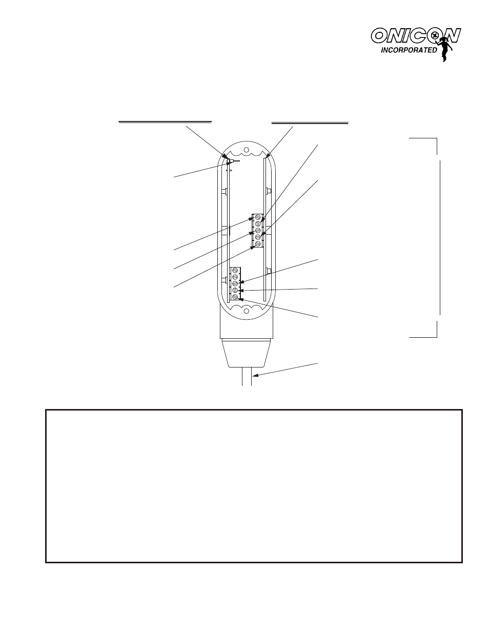
SENSING BOARD
TEST SIGNAL INPUT
COMMON GROUND
(BLACK WIRE)
FREQUENCY OUTPUT
(GREEN WIRE)
+24V AC/DC SUPPLY
(RED WIRE)
BOTTOM TURBINE:
F-1200 ONLY
(ORANGE WIRE)
FREQUENCY BOARD
TOP TURBINE:
F-1200 ONLY
(WHITE WIRE)
EXTERNAL
CABLE CONNECTIONS
GREEN WIRE (BOARD TO BOARD)
RED WIRE (BOARD TO BOARD)
BLACK WIRE (BOARD TO BOARD)
EXTERNAL CABLE
NOTE: INTERNAL CONNECTIONS
OMITTED FOR CLARITY
1500 North Belcher Road, Clearwater, FL 33765 • Tel (727) 447-6140 • Fax (727) 442-5699 • [email protected]
WIRING DIAGRAM
INTERNAL CONNECTIONS FOR FREQUENCY
OUTPUT FLOW METERS
MODELS F-1100 / F-1200 / F-1300
For use with serial numbers 115692 and later
0066-1