Standard thermowell assembly – ONICON System-10 BTU User Manual
Page 14
11451 Belcher Road South, Largo, FL 33773 • USA • Tel +1 (727) 447-6140 • Fax (727) 442-5699 • [email protected]
System-10 BTU Meter Manual 03/15 - 0651-16 / 18323
Page
14
9-10-01
SYSTEM-10 BTU METER
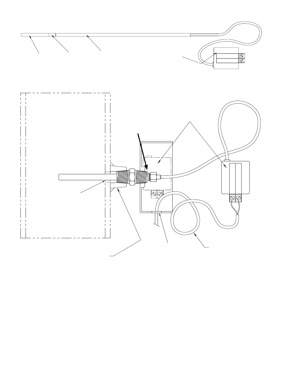
STANDARD TEMPERATURE SENSOR ASSEMBLY
0286
A-6
INCORPORATED
MODULE
ELECTRONICS
SLEEVE
(Length varies with
thermowell length)
SPACER
END PIECE
PLASTIC
SENSOR
TEMPERATURE
SIGNAL (RED)
REFERENCE (BLACK)
SUPPLY
S/N 123456
ONICON TEMPERATURE SENSOR
TEMPERATURE SENSOR INSTALLED IN THERMOWELL
STANDARD THERMOWELL ASSEMBLY
FOR SYSTEM-10 BTU METER
SHOWN WITH TEMPERATURE SENSOR
0284
9-5-01
SIGNAL (RED)
REFERENCE
(BLACK)
SUPPLY
S/N 123456
5/8" MINIMUM
HOLE SIZE
1/2" HOLE FOR
CONDUIT OR
STRAIN RELIEF
FITTING.
NOTES: 1. If additional couplings are required, ensure that tip of thermowell remains in flow stream.
A-2
INCORPORA TED
1500 North Belcher Road, Clearwater, Florida 33765 Tel (727) 447-6140 Fax (727) 442-5699
www.onicon.com E-mail: [email protected]
PROVIDE 18-22 GA TWISTED
SHIELDED PAIR.
COIL ONE FOOT OF EXTRA
CABLE IN CONDUIT BOX.
1/2” NPT WELDED
BRANCH OUTLET
PLACE ELECTRONICS
MODULE IN BOX AFTER
CONNECTING WIRES.
RETAINING NUT
(Do not overtighten)
3.2.4 Flow Meter Installation
Determine which pipe (supply or return) has the longer unobstructed straight run. Install
the flow meter in the longest straight pipe run available. One temperature sensor can be
installed five diameters downstream of the flow meter leaving enough clearance to remove
either sensor from the pipe without interference from the other sensor.
Also refer to the installation manual and/or other documentation that is provided with
your ONICON flow meter.
For F-1300 series inline turbine flow meters, refer to the documentation that is provided
with the flow meter.