Auxiliary flow meter signals, Flow meter inputs, System-10 btu meter mother board – ONICON System-10 BTU User Manual
Page 45: Shield, Insertion turbine flow meter input connections, G60hz, Factory installed cable
11451 Belcher Road South, Largo, FL 33773 • USA • Tel +1 (727) 447-6140 • Fax (727) 442-5699 • [email protected]
System-10 BTU Meter Manual 03/15 - 0651-16 / 18323
Page A-11
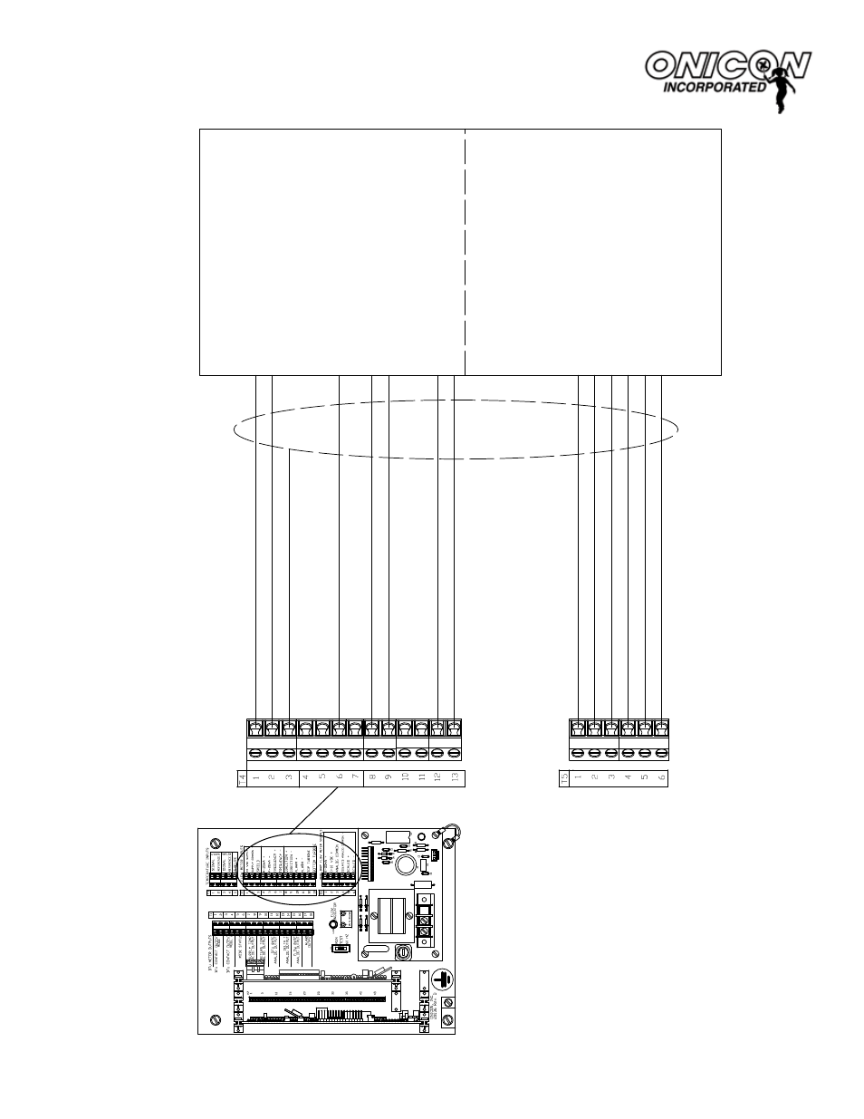
SYSTEM-10 BTU METER MOTHER BOARD
Insertion Turbine Flow Meter Input Connections
Connections shown with (E) are used with F-x30 models, including bi-directional.
Connections shown with (D) are used with F-x
11 models, including
bi-directional.
Connections shown with (C) are used with F-x10 models, including bi-directional.
(D) Isolated
Analog Common - (
Yellow)
Connections shown are for flow meter output signals not used by the Btu mete
r.
Both incoming and outgoing connections are made to the same terminal.
Auxiliary Flow Meter Signals
* Shield
Flow Meter Inputs
For F-1x10, F-1x
11 & F-1x30
(E) Scaled - (Brown)
(E) Scaled + (Blue)
(C or D) 0-10 VDC + (Brown)
(C or D) 4-20m
A + (Blue)
Connections shown with (B) are required for all dual turbine models, including bi-directional.
Connections shown with (A) are required for all bi-directional models.
Connections shown with * are required for all models.
F-
1100, F-1200 & F-1300 Series
Flow Meter Connections
(B) Bottom
T
urbine (Orange)
(B)
T
op
T
urbine (White)
(A) Direction - (
Violet)
(A) Direction + (Grey)
* Frequency + . (Green)
* Supply Common - (Black)
* 24VDC Supply + (Red)
J1
5
G
60HZ
1
J2-1
+15
+24
J2-12
G
G
10
R7
H3
R1
20
075-50
REV. A
LED1
T1
D1
D2
V
AR1
F1
1/8 AMP
TB1
D4
D3
H1
1
Factory Installed Cable
L1
N
Not Used