ONICON System-10 BTU User Manual
Page 25
11451 Belcher Road South, Largo, FL 33773 • USA • Tel +1 (727) 447-6140 • Fax (727) 442-5699 • [email protected]
System-10 BTU Meter Manual 03/15 - 0651-16 / 18323
Page
25
SECTION 4.0: SYSTEM-10 START-UP AND COMMISSIONING
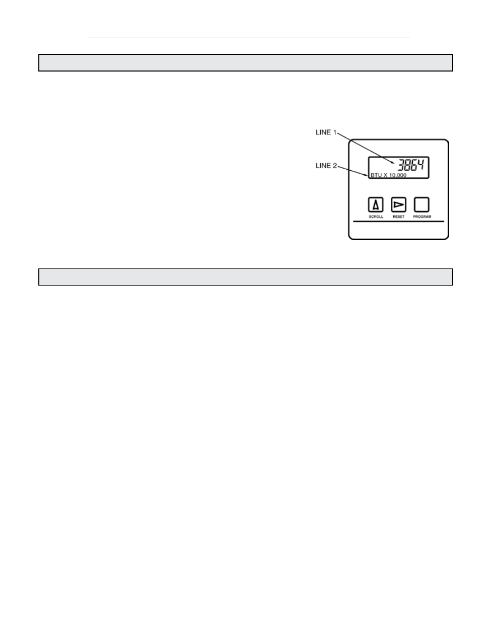
4.1 DISPLAY AND KEYPAD
The display contains two lines of alphanumeric characters. The first line displays the current
value. The second line contains the engineering units and a multiplier which can range from
1 to 1,000,000. The multiplier is the value the number on the top line must be multiplied by to
achieve the correct value.
Three membrane keys are provided to operate the display
and program the meter.
When operating in the run mode, the SCROLL button
advances the display from one page to the next. A total
of up to 11 different pages may be available for display
depending whether the meter is operating in the single or
dual mode.
The RESET button (if enabled) allows totals to be reset to
zero. The PROGRAM button is not active when operating
in the run mode.
4.2 PROCESSOR START-UP
When power is applied to the Btu meter alphanumeric characters appear on the two lines of the
display indicating the meter is operating. Press and release the SCROLL button on the front panel.
Observe the display cycle to the next display page.
Select the SUPPLY TEMP Page. Note the displayed temperature. Confirm that it is in the expected
range. Now select the RETURN TEMP page. Again note the displayed temperature. Confirm that it
is also in the correct range.
Select the FLOW RATE page. Note the displayed flow rate. Confirm that the flow rate value is in
the correct range.
Successively pressing the SCROLL button will cycle the display through the run mode pages
summarized in the tables on the next page.
To finalize the installation, follow the procedure outlined in section 4.5 to identify and designate
the flow meter location.