ONICON System-10 BTU User Manual
Page 28
11451 Belcher Road South, Largo, FL 33773 • USA • Tel +1 (727) 447-6140 • Fax (727) 442-5699 • [email protected]
System-10 BTU Meter Manual 03/15 - 0651-16 / 18323
Page
28
4.6 COMMISSIONING
Upon initial installation, it is strongly recommended that
both the System-10 and its associated flow meter be
commissioned to ensure that they are properly installed
and functioning correctly. This process involves verifying
the mechanical installation, measuring flow and
temperature signals and then comparing these
measurements to the specified installation and operating
parameters listed on the certificate of calibration
provided with the meter. The data collected during this
initial commissioning process will then serve as baseline
data for periodic revalidation of the meter operation.
COMMISSIONING PROCEDURE - ONICON BTU METERS
Please read all installation instructions carefully before proceeding. Wiring diagrams are located in the
appendix of this manual. Use the Btu meter certificate of calibration to verify that the specified
installation & operating parameters match the actual conditions at the location where the meter is
installed. A worksheet for checking off these steps and recording measured values is located on the
following page.
1.
Confirm flow meter
location and adequate
straight pipe run to
achieve desired results.
Confirm that the flow
meter location is iden-
tified and selected as
per section 4.5 of this
manual.
Is the flow meter located in the correct location as required by the plans?
Compare actual straight pipe upstream and downstream of the flow meter
location to the recommended distances identified in the flow meter installation
manual.
Note: The flow meter manual is very conservative, assuming worst-case pipe
obstructions. Contact ONICON to discuss specifics of your application. If
straight pipe run is very short, consult ONICON PRIOR to installing the flow
meter to discuss the possibility of upgrading to a different flow meter.
Review and record the flow meter location program setting.
2.
Confirm pipe size &
material.
Confirm that the flow meter is tagged for the pipe diameter and material it is
installed in and that this information corresponds to the information listed
on the Btu meter certificate of calibration. When in doubt, measure the
circumference of the pipe.
Pipe O.D. = (circumference / 3.14) – (insulation thickness x 2)
3.
Confirm insertion
depth and orientation
(for insertion meters
only).
Each insertion type flow meter comes with an attached insertion gage and
instruction tag. Ensure that meter is inserted to correct depth and that the
electronics enclosure is parallel with the pipe, with the arrow in the direction
of flow.
4.
Confirm temperature
sensor thermowell
installations.
Confirm that the thermowells are properly installed and the bottom of the well
is in the flow stream. Make certain that only the components supplied with the
installation kit were used and that additional bushings were not added.
5.
Confirm temperature
sensor installations.
Confirm that the temperature sensors are properly installed, and each sensor is
bottomed out in the well. A small amount of thermal compound should be
applied to the tip of each sensor to improve the thermal transfer.
Each sensor has a black sleeve on the cable coming up from the metal sensor.
This sleeve in cut to length for the thermowell. When the sensor is fully
bottomed out in the well, the retaining nut can be tightened without any of the
black sleeve protruding through the nut.
6.
Confirm connection to
correct ONICON Btu
meter.
Confirm that the flow meter serial number matches the Btu meter serial
number (when ordered together). Also confirm that the serial numbers of the
temperature sensors match the Btu and flow meters.
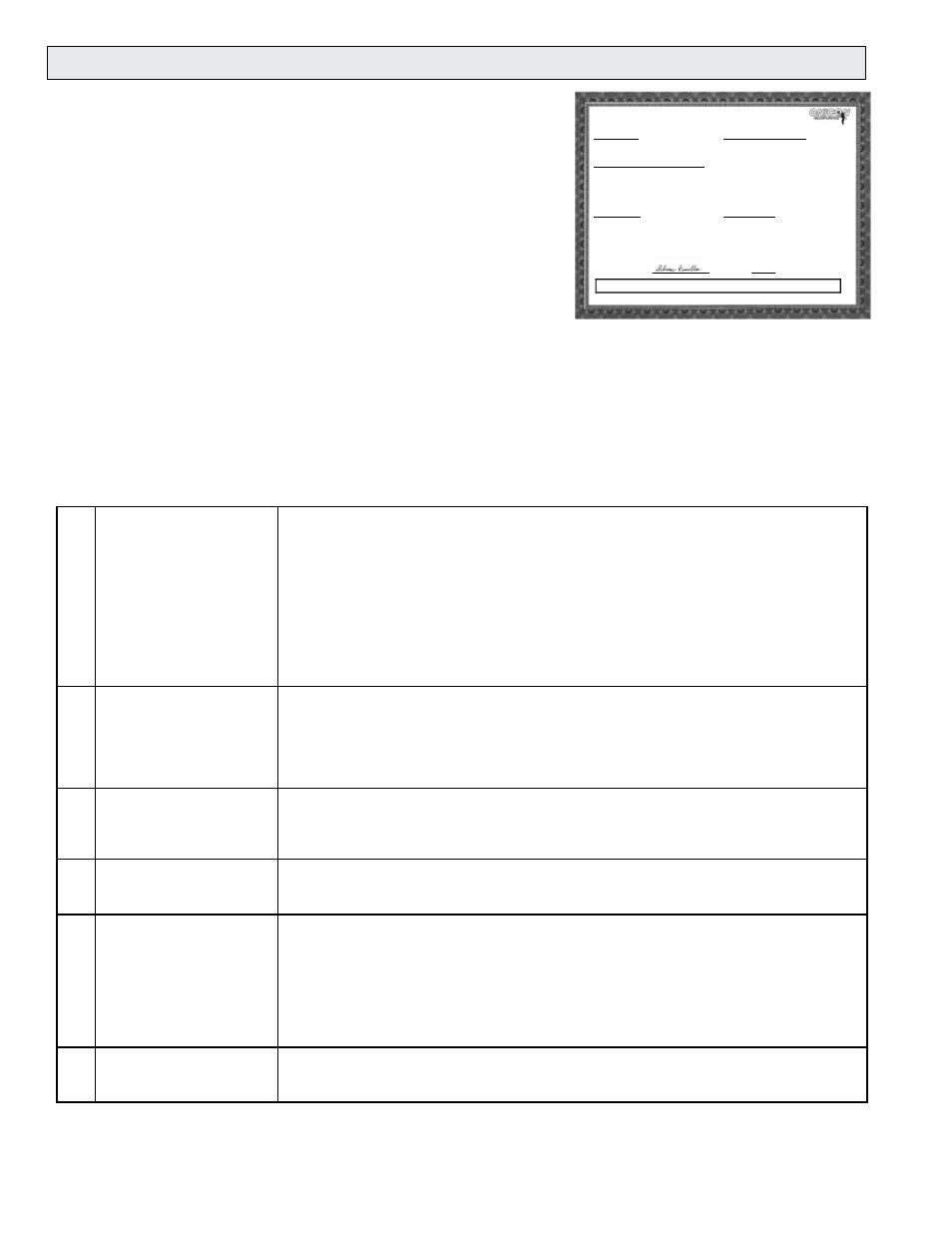
INTEGRATED BTU METER
CERTIFICATE OF CALIBRATION
METER INFORMATION
Meter Tag:
BTU Meter Model: SYSTEM-30
Serial No: 134036
SPECIFIED INSTALLATION & OPERATING PARAMETERS
Pipe Information: 1 Inch Copper Tube
Design Maximum Flow Rate: 40.0 GPM
Design Supply Temperature: MODE 1: 45°F
Design Return Temperature: MODE 1: 55°F
Fluid: 25% Ethylene Glycol
Fluid Specific Heat: 0.885 BTU/lb°F
Fluid Density:
65.06 lb/ft³
CONFIGURATION DATA
Enclosure Type:
Input Supply Voltage: 24 AC/DC
Thermowell Type:
CALIBRATION AND PROGRAMMING DATA
Firmware Version:
CFM4.6S30
Communications Protocol:
Device Network Address:
Flow Sensor MF Code: 547.500
Programmed Units & Multipliers:
Energy Total: BTU x 1K
Energy Rate: BTU/HR x 1K
Flow Total: GAL x 10
Flow Rate: GPM x 1
Temperature: °F
Damping: 5
Pulse Duration: 500 ms
Supply Temperature Slope: 9.969
Offset: -0.870
Return Temperature Slope: 10.004
Offset: -0.130
OUTPUT SIGNAL SCALING
Energy Total(s): 1 Pulse = BTU x 1K
Flow Rate: NA
Energy Rate: NA
Supply T:
NA
Return T:
NA
Delta T:
NA
Calibrated By:
Date:
09/01/2004
1500 North Belcher Road, Clearwater, Florida 33765 Tel (727) 447-6140 Fax (727) 442-5699
ONICON Incorporated certifies that the flow and temperature sensors provided with this Btu meter have been individually calibrated based on the
application specific data provided above; using standards directly traceable to the U.S. National Institute of Standards and
Technology (N.I.S.T.).
Shane Hamilton