Auxiliary flow meter signals, Flow meter inputs, Shield – ONICON System-10 BTU User Manual
Page 19: F-2000 flow meter connections
11451 Belcher Road South, Largo, FL 33773 • USA • Tel +1 (727) 447-6140 • Fax (727) 442-5699 • [email protected]
System-10 BTU Meter Manual 03/15 - 0651-16 / 18323
Page
19
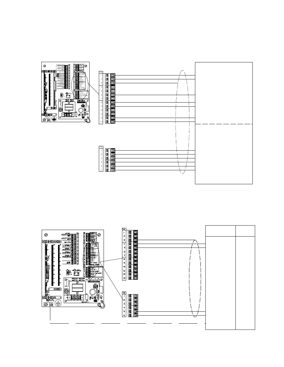
3.3.2.2 Input Signal Connections From Insertion Turbine Flow Meters
ONICON turbine flow meters are provided with a number of different output
configurations. These affect the number of wires contained in the cable attached
to the flow meter. Refer to the diagram below and the laminated tag attached to
the flow meter for specific details.
Connections shown with (E)
are used with F-x30 models, including
bi-directional.
Connections shown with (D)
are used with F-x11 models, including
bi-directional.
Connections shown with (C)
are used with F-x10 models, including
bi-directional.
(D) Isolated Analog Common - (Yellow)
Connections shown are for flow meter
output signals not used by the Btu meter.
Both incoming and outgoing connections
are made to the same terminal.
Auxiliary Flow Meter Signals
* Shield
Flow Meter Inputs
For F-1x10, F-1x11 & F-1x30
(E) Scaled - (Brown)
(E) Scaled + (Blue)
(C or D) 0-10 VDC + (Brown)
(C or D) 4-20mA + (Blue)
Connections shown with (B)
are required for all dual turbine models,
including bi-directional.
Connections shown with (A)
are required for all
bi-directional models.
Connections shown with * are
required for all models.
F-1100, F-1200 & F-1300 Series
Flow Meter Connections
(B) Bottom Turbine (Orange)
(B) Top Turbine (White)
(A) Direction - (Violet)
(A) Direction + (Grey)
* Frequency + . (Green)
* Supply Common - (Black)
* 24VDC Supply + (Red)
J1
5
G
60
HZ
1
J2-1
+15
+24
J2-12
G
G
10
R7
H3
R1
20075-50 REV. A
LED1
T1
D1
D2
VAR1
F1
1/8 AMP
TB1
D4
D3
H1
1
Factory Installed Cable
L1
N
Not Used
3.3.2.3 Input Signal Connections From F-2500 Flow Meters
* 4-20mA -
* 4-20mA +
F-2000 Flow Meter
Connections
(A) Scaled +
(A) Scaled -
Flow Meter Inputs
* Shield
Auxiliary Flow Meter Signals
* Earth
Outputs
Terminal #
* + 24V
* - ILoop
+ 24V
- Pout
* Earth
Connections shown with * are required for all installations. Connections shown with (A) are optional.
1
2
3
4
L1 N
Not Used
Flow Meter Inputs
Flow Meter Inputs