ONICON System-10 BTU User Manual
Page 31
11451 Belcher Road South, Largo, FL 33773 • USA • Tel +1 (727) 447-6140 • Fax (727) 442-5699 • [email protected]
System-10 BTU Meter Manual 03/15 - 0651-16 / 18323
Page
31
SECTION 5.0: DIAGNOSTICS
5.1 DIAGNOSTICS
The ONICON System-10 BTU Meter uses a microprocessor
to calculate energy. Factory programmed settings provide
rate and total values in accordance with the customer’s
application data. Refer to the Btu meter certificate of
calibration for a complete listing of factory settings. These
settings may be reviewed and changed with assistance from
ONICON.
The System-10 BTU Meter is also equipped with diagnostic
indicator lights and self diagnostic test signals that confirm
the operation of the microprocessor and its input circuitry.
Please contact ONICON if any of the diagnostic lights or
test signals listed below indicates a potential problem with
the operation of the Btu meter.
5.1.1 Diagnostic Lights
Low Voltage Power Supply
Located on the power supply board inside the System-10 BTU Meter (refer to A-15),
is a single LEDs that will illuminat when +15 VDC is present.
Liquid Flow
Located in the center of the motherboard (refer to A-12) next to terminal block T5, the
LED will flash at a rate that is proportional to the liquid flow rate for frequency flow
signals. For 4 - 20 mA signals, the light will stay lit whenever the output is greater than
4 mA. An unlit LED indicates no flow signal.
5.1.2 Flow Test Signals
Flow Test
Located in the center of the motherboard (Refer to A-13) immediately above the power
supply board is a three position slide switch used to test the flow input. When the switch
is in the top position, the Btu meter input is connected to the flow meter. When the switch
is in the middle position, the Btu meter input is connected to two test terminals used to
apply a variable frequency to simulate flow. When the switch is in the bottom position,
the Btu meter input is connected to a 50/60 Hz signal that simulates a fixed flow rate.
Refer to the Btu meter certificate of calibration to determine the correct display reading
when operating in the 50/60 Hz test mode.
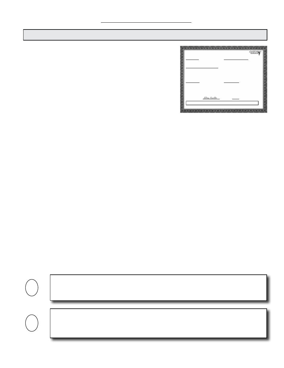
INTEGRATED BTU METER
CERTIFICATE OF CALIBRATION
METER INFORMATION
Meter Tag:
BTU Meter Model: SYSTEM-30
Serial No: 134036
SPECIFIED INSTALLATION & OPERATING PARAMETERS
Pipe Information: 1 Inch Copper Tube
Design Maximum Flow Rate: 40.0 GPM
Design Supply Temperature: MODE 1: 45°F
Design Return Temperature: MODE 1: 55°F
Fluid: 25% Ethylene Glycol
Fluid Specific Heat: 0.885 BTU/lb°F
Fluid Density:
65.06 lb/ft³
CONFIGURATION DATA
Enclosure Type:
Input Supply Voltage: 24 AC/DC
Thermowell Type:
CALIBRATION AND PROGRAMMING DATA
Firmware Version:
CFM4.6S30
Communications Protocol:
Device Network Address:
Flow Sensor MF Code: 547.500
Programmed Units & Multipliers:
Energy Total: BTU x 1K
Energy Rate: BTU/HR x 1K
Flow Total: GAL x 10
Flow Rate: GPM x 1
Temperature: °F
Damping: 5
Pulse Duration: 500 ms
Supply Temperature Slope: 9.969
Offset: -0.870
Return Temperature Slope: 10.004
Offset: -0.130
OUTPUT SIGNAL SCALING
Energy Total(s): 1 Pulse = BTU x 1K
Flow Rate: NA
Energy Rate: NA
Supply T:
NA
Return T:
NA
Delta T:
NA
Calibrated By:
Date:
09/01/2004
1500 North Belcher Road, Clearwater, Florida 33765 Tel (727) 447-6140 Fax (727) 442-5699
ONICON Incorporated certifies that the flow and temperature sensors provided with this Btu meter have been individually calibrated based on the
application specific data provided above; using standards directly traceable to the U.S. National Institute of Standards and
Technology (N.I.S.T.).
Shane Hamilton
IMPORTANT NOTE
The second line of the display will alternate between TEST MODE and the normal display of
engineering units and multipliers whenever the flow test switch is in the TEST or 60 Hz positions.
i
IMPORTANT NOTE
After operating for five minutes in either the TEST or 60 Hz mode, the displayed flow and energy
rate will be disabled, and the meter will report a zero flow rate and a zero energy rate to the
network. The meter will remain in this state until the switch is set to RUN.
i