Flow meter inputs, Auxiliary flow meter signals, Caution – ONICON System-10 P1 User Manual
Page 21: Shield, Earth (green/yellow), G60hz, Led1 t1, Var1
11451 Belcher Road South, Largo, FL 33773 • USA • Tel +1 (727) 447-6140 • Fax +1 (727) 442-5699 • [email protected]
System-10-P1 Manual 10/14 - 0656-9 / 18320
Page 21
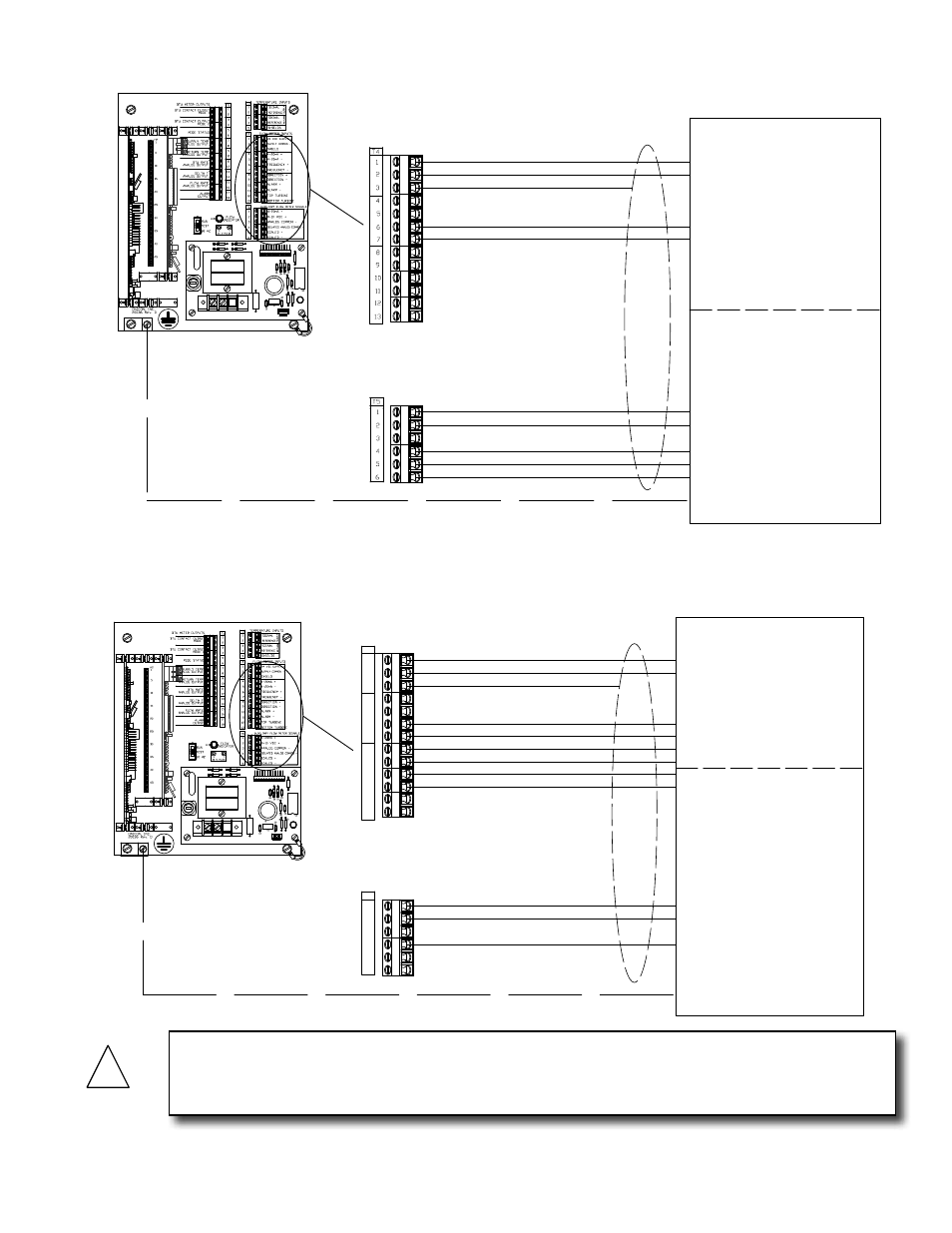
3.3.2.7 Input Signal Connections from FB-3500 Flow Meter
J1
5
G
60HZ
1
J2-1
+1
5
+24
J2-12
G
G
10
R7
H3
R1
20075-50 REV. A
LED1
T1
D1
D2
VAR1
F1
1/8 AMP
TB1
D4
D3
H1
1
Connections shown for T5-1 and T5-2
are for the same analog output from the
FB-3500. This output can be configured in
the flow meter as a 4-20mA or 0 -10 VDC.
0-10 VDC + (Blue)
* Frequency - (Yellow)
* 24VDC Supply + (Red)
* Supply Common - (Black)
* Frequency + (Green)
FB-3500 Flow Meter Connections
Connections shown with * are required.
4-20mA + (Blue)
Flow Meter Inputs
* Shield
Auxiliary Flow Meter Signals
Isolated Analog Common - (Brown)
Earth (Green/Yellow)*
Factory Installed Cable
T4
1
2
3
4
5
6
7
8
9
10
11
12
13
* Direction - (White / Black)
* Direction + (Orange / Black)
T5
1
2
3
4
5
6
Alarm - (White)
Alarm + (Orange)
Connections shown below dashed line
are for flow meter output signals not used
by the BTU meter. Both incoming and
outgoing connections are made to the
same terminal.
L1 N
Not Used
!
CAUTION
See FB-3500 installation and operation guide for additional information on properly grounding
the meter.
3.3.2.6 Input Signal Connections from F-3500 Flow Meter
J1
5
G
60HZ
1
J2-1
+1
5
+24
J2-12
G
G
10
R7
H3
R1
20075-50 REV. A
LED1
T1
D1
D2
VAR1
F1
1/8 AMP
TB1
D4
D3
H1
1
Connections shown for T5-1 and T5-2
are for the same analog output from the
F-3500. This output can be configured in
the flow meter as a 4-20mA or 0 -10
VDC.
0-10 VDC + (Blue)
* Frequency - . (Yellow)
* 24VDC Supply + (Red)
* Supply Common - (Black)
* Frequency + . (Green)
F-3500 Flow Meter Connections
Connections shown with * are
required for all models.
Connections shown with (A)
are required for all
bi-directional models.
Connections shown with (B)
are required for all dual turbine models,
including bi-directional.
4-20mA + (Blue)
Scaled + (Gray)
Scaled - (Violet)
Flow Meter Inputs
* Shield
Auxiliary Flow Meter Signals
Connections shown are for flow meter
output signals not used by the Btu meter.
Both incoming and outgoing connections
are made to the same terminal.
Isolated Analog Common - (Brown)
Earth (Green/Yellow)
Factory Installed Cable
L1 N
Not Used