ONICON System-10 P1 User Manual
Page 26
11451 Belcher Road South, Largo, FL 33773 • USA • Tel +1 (727) 447-6140 • Fax +1 (727) 442-5699 • [email protected]
System-10-P1 Manual 10/14 - 0656-9 / 18320
Page 26
3.3.6 Optional Isolated Digital Pulse Input (Di3)
The System-10-P1 BTU Meter can be provided with an optional auxiliary input pulse
counter. This option allows the System-10-P1 BTU Meter to receive a pulse input from an
external device, such as a power meter or gas meter for example, and totalize these pulses
on an internal register and communicate this value via the P1 communications network.
This register can be zeroed on demand via the network. The P1 communications board
with the auxiliary input feature must be specified at time of order to receive this feature.
The input pulse must meet the following criteria:
1. Frequency Input Range, 50 Hz maximum
2. 10 milli-second minimum pulse duration
Input Pulse Definition:
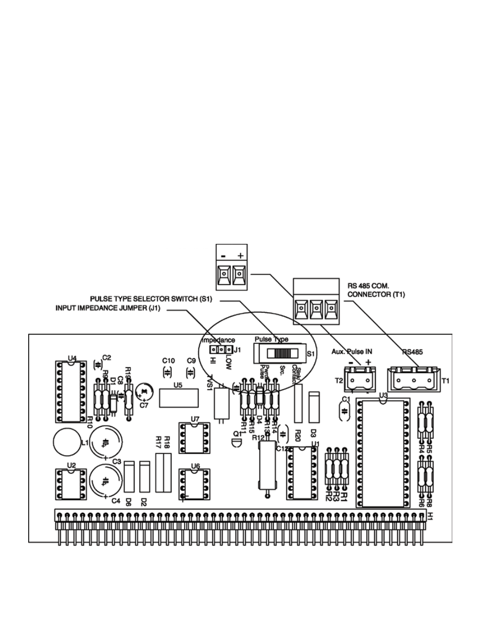
In order to configure the communications card for an auxiliary input pulse, you
must first determine which type of pulse your meter produces. The allowable
types of input pulses are described below. Based on the type of pulse, set the
selector switch (S1) on the communications Circuit Board (Fig. 1) to the correct
setting.
Fig. 1
AUX PULSE INPUT (Di3)
CONNECTOR (T2)