ONICON System-10 P1 User Manual
Page 31
11451 Belcher Road South, Largo, FL 33773 • USA • Tel +1 (727) 447-6140 • Fax +1 (727) 442-5699 • [email protected]
System-10-P1 Manual 10/14 - 0656-9 / 18320
Page 31
4.5 ENTERING A NETWORK ADDRESS, SELECTING THE FLOW METER LOCATION &
ENABLING / DISABLING FRONT PANEL RESET
Before the System-10 can communicate on the P1 network, the flow meter location should be
programmed into the meter and the appropriate network address must set.
Identifying the flow meter location is particularly important for systems that will operate with
delta temperatures ≥20 °F. The default setting for the flow meter location is unknown. It should
be changed to the location setting that corresponds to the flow meter’s physical location in the
piping system. Choose supply when the flow meter is located in the pipe leading to the inlet to
the heat exchanger and return when the flow meter is located in the pipe leaving the outlet of
the heat exchanger. Leave the setting at unknown for bi-directional flow applications.
The application number is programmed into the meter at the factory prior to delivery, based on
the application information supplied by the customer. This application number can be changed
if necessary. Contact ONICON for additional instructions prior to attempting to change the
application number.
The System-10-P1 BTU Meter accumulates energy and volume totals in nonvolatile memory.
This memory can be zeroed directly at the meter or via the network. The direct method requires
the operator to scroll through the display menu pages until the subject energy or volume total is
displayed. The operator must then press the reset button on the front panel. The selected total
will then reset to zero. The next total to be zeroed is selected and the process repeated. The
front panel reset function, however, must be enabled for this to occur. It is disabled by default.
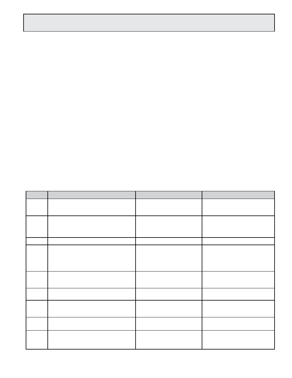
To select the flow meter location, enter a new device address or enable the front panel reset,
follow the instructions in the table below.
STEP
ACTION
REACTION
COMMENT
0
Obtain a device address from the
network administrator.
The device address is a three
digit number between 001 -
099, excluding zero.
1
With the meter running, open the
front panel and locate switch DEV
ADD/PROG ENAB. Press DEV ADD/
PROG ENAB and then release it.
None
The DEV ADD/PROG ENAB is
located on the heat computer
board. (See appendix page
A-9.)
2
Close the front panel.
3
Press the PROGRAM button. (If you
do not press the PROGRAM button,
the meter will revert to the RUN mode
after 5 minutes.)
The System-10 changes to
PROGRAM mode and the
DEVICE ID page will appear
with the first digit of the
address flashing.
The PROGRAM button is on
the front panel.
4
Successively press the SCROLL
button to increment the number to the
desired value from 0-9.
The number increments by
one each time you press the
button.
The SCROLL button is on the
front panel.
5
Press the RESET button.
The second character blinks. The RESET button is on the
front panel.
6
Successively press the SCROLL
button to increment the number to the
desired value from 0-9.
The number increments by
one each time you press the
button.
The SCROLL button is on the
front panel.
7
Press the RESET button.
The third character blinks.
The RESET button is on the
front panel
8
Successively press the SCROLL
button to increment the number to the
desired value from 0-9.
The number increments by
one each time you press the
button.
The SCROLL button is on the
front panel.