St andard thermowell assmebl y, Standard thermowell assembly – ONICON System-10 P1 User Manual
Page 44
11451 Belcher Road South, Largo, FL 33773 • USA • Tel +1 (727) 447-6140 • Fax +1 (727) 442-5699 • [email protected]
System-10-P1 Manual 10/14 - 0656-9 / 18320
A - 2
0284
9-5-01
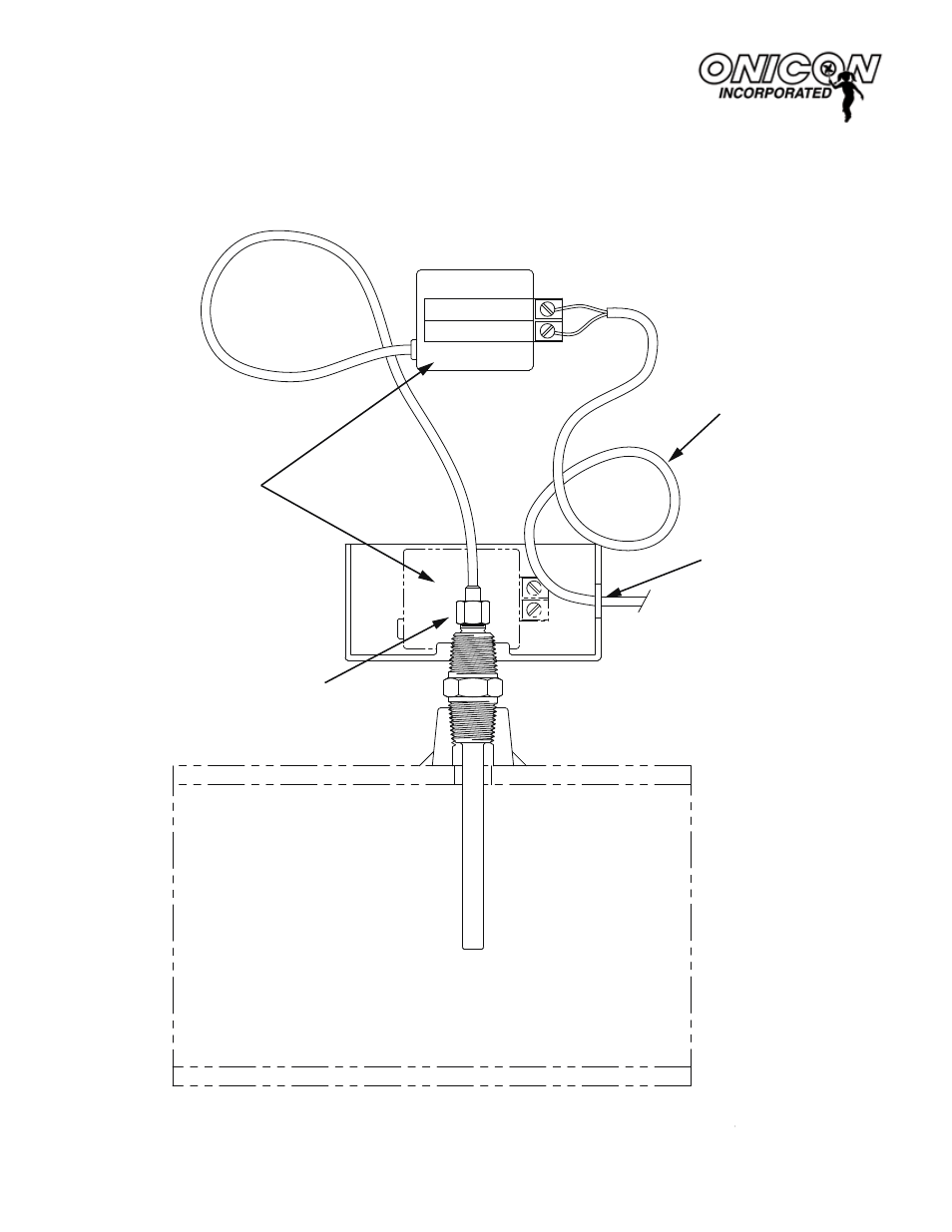
NOTES:
1. If additional couplings are required, ensure that tip of thermowell remains in flow stream.
A-2
1500 Nor
th Belc
her Road,
Clearwater
, Florida 33765
Tel (727) 447-6140 F
ax (727) 442-5699
www
.onicon.com E-mail:
ST
ANDARD THERMOWELL ASSMEBL
Y
FOR SYSTEM-10 BTU METER
SHOW WITH TEMPERA
TURE SENSOR
PLACE ELECTRONICS MODULE IN BOS
AFTER
CONNECTING WIRES.
PROVIDE #18-22 TWISTED SHIELDED P
AIR. COIL
ONE FOOT OF EXTRA
CABLE IN CONDUIT BOX.
1/2” HOLE FOR CONDUIT OR STRAIN RELIEF FITTING.
RET
AINING NUT
(Do NOT Overtighten)
SUPPLY
SIGNAL (RED)
REFERENCE (BLACK)
S/N 123456
STANDARD THERMOWELL ASSEMBLY
For System-10 Btu Meter Shown with Temperature Sensor