ONICON System-10 P1 User Manual
Page 49
11451 Belcher Road South, Largo, FL 33773 • USA • Tel +1 (727) 447-6140 • Fax +1 (727) 442-5699 • [email protected]
System-10-P1 Manual 10/14 - 0656-9 / 18320
A - 7
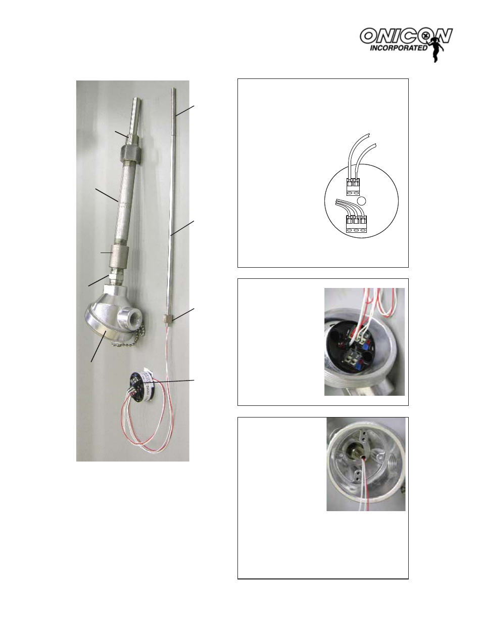
STANDARD INSTALLATION DETAIL FOR
HEAVY DUTY THERMOWELL
In Welded Pipe
1500 North Belcher Road, Clearwater
, FL
33765 • T
el (727) 447-6140 • Fax (727) 442-5699
www
.onicon.com • [email protected]
1/2” coupling
1/2” extension
nipple
heavy-duty thermowell with 1/2” NPT
process
thread (length varies with
pipe size)
Step 1: Drill 7/8” hole in pipe. Install thermowell using fittings supplied by ONICON.
Complete steps 2-4 only after all welding, brazing & soldering are complete.
NOTE: Each sensor and transmitter are factory matched to each other and to a particular System-10 BTU Meter
.
connection
head
1/2” fitting
transmitter
retainer nut
(finger tighten only)
SS spacer sleeve (length varies with thermowell length)
platinum R
TD
Step 2: Remove lid and insert R
TD assembly into
thermowell, ensuring that it bottoms out.
Thermal compound may be used; apply only a pea-sized amount to the tip of the R
TD
prior to insertion.
Thread retaining nut onto fitting at bottom of connection head and hold sensor in place while tightening the nut by hand.
DO NOT OVER
TIGHTEN.
Step 3: Place the transmitter onto the exposed end of the SS spacer sleeve, gently guiding the excess wire through the center hole of the transmitter
.
Use caution to avoid pinching the wires or pulling the sensor out of the thermowell.
Step 4: Connect field wires from the System-10 BTU Meter to the transmitter as shown.
Carefully coil extra wire and thread the lid onto the connection head.
TRANSMITTER WIRING
REFERENCE
SIGNAL
TO BTU METER
TO
RT
D
HEA
VY DUTY THERMOWELLS FOR SYSTEM-10 BTU METERS
FOR PROCESS TEMPERA
TURES OVER 300
° F
0499-2
07-10