Research Concepts RC4000 User Manual
Page 119
RC4000 Antenna Controller
Chapter 4
Support
111
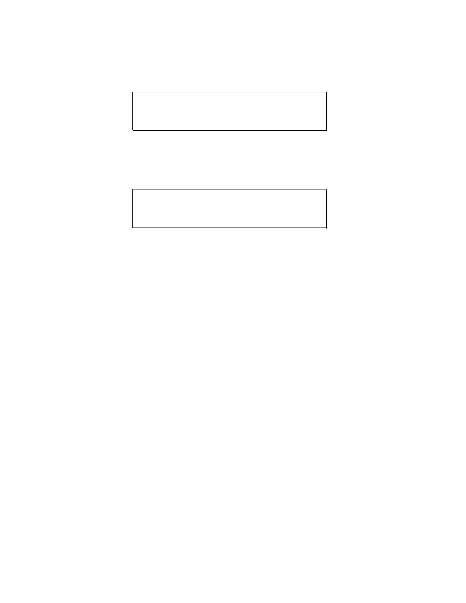
One of the MAINTENANCE screens used is the Analog to Digital Voltage screen (see 3.3.2.1). This
screen shows raw data coming from antenna position sensors (potentiometers and resolvers).
AZ: 1.114 181.30 33004 AD VOLTAGES
EL: 1.143 1 122.30 22264 22.3 L1:1
POL:2.237 181.30 33044 L2:1
SIG: 3.756(1) <1>RF <2>SS1 <3>SS2 <4>GND
Another MAINTENANCE screen that will be used is the Limits Maintenance screen ( see 3.3.2.5). This
screen shows the current sensed state of limit switches for all three axes.
AZIM CW:0 CCW:1 STOW:0 (0-OFF) LIMITS
ELEV UP:1 DN:1 STOW:1 (1- ON) ACTIVE
POL CW:0 CCW:1 STOW:0
<BKSP>MAKE LIMITS INACTIVE <MODE>EXIT
Before beginning axes calibration, the installer should become familiar with accessing these screens.