Research Concepts RC4000 User Manual
Page 32
RC4000 Antenna Controller
Chapter 2
Hardware
24
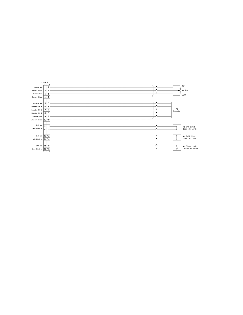
2.1.2.2.15 J14A - Azimuth Sensors
J14A "none" 16 pin Type 10
J14 provides a double row of pins. The top 16 pins are designated "J14A" and are typically allocated to
supporting potentiometer, pulse and limit switch feedback from the azimuth axis.
The + side of each limit switch circuit supplies 12 VDC. This 12 VDC supply is protected by a resettable
fuse rated at 250 mA.
The azimuth stow switch must be closed when at the azimuth stow position. If the azimuth stow limit
switch cable is severed, the RC3000 will think that the azimuth axis is not at the stowed position. Logic
within the RC3000 will not allow elevation to move below the elevation down limit switch if an azimuth
stowed condition is not recognized.
The directional sense of azimuth movement is defined as clockwise (CW) or counter-clockwise (CCW),
as viewed by an observer located above the antenna. On the controller, CW movement results in a
greater sensed azimuth position.