Research Concepts RC4000 User Manual
Page 33
RC4000 Antenna Controller
Chapter 2
Hardware
25
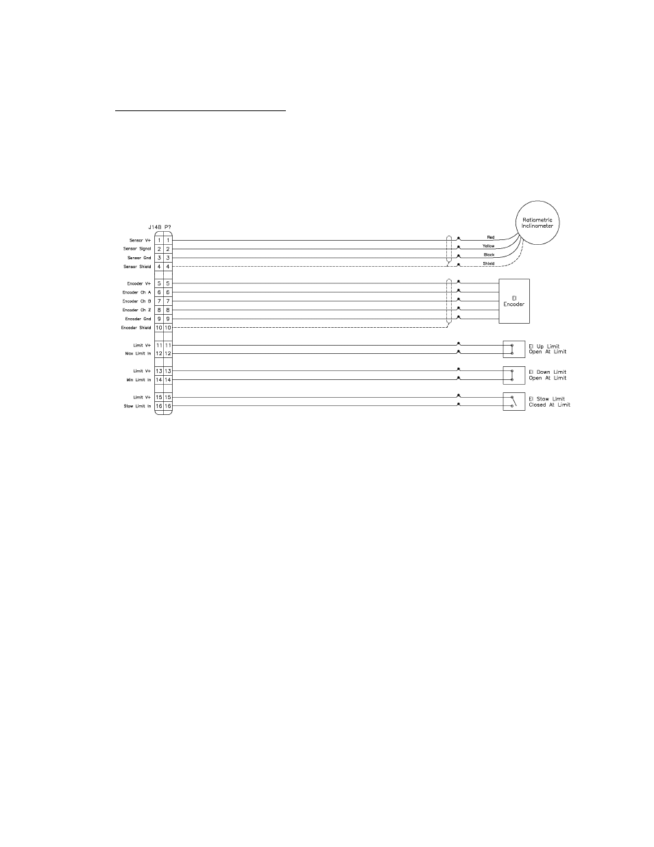
2.1.2.2.16 J14B - Elevation Sensors
J14B "none" 16 pin Type 10
J14 provides a double row of pins. The bottom 16 pins are designated "J14B" and is typically allocated to
supporting inclinometer, pulse and limit switch feedback from the elevation axis.
The elevation up switch must be open when the elevation axis has reached the up limit. If the elevation
up limit switch cable is severed, the RC4000 will think that the elevation axis is at the up limit. Logic
within the RC4000 will not allow the elevation axis to move up if an up limit condition is recognized.
The elevation down switch must open when the elevation axis has reached the down limit. If the
elevation down limit switch cable is severed, the RC4000 will think that the elevation axis is below the
down limit. Logic within the RC4000 will not allow the azimuth axis to move when the elevation down
condition is recognized.
The elevation stow switch must open when the elevation axis has reached the stow position. If the
elevation stow limit switch cable is severed, the RC4000 will think that the elevation axis is at the stow
position. Logic within the RC4000 will not allow the elevation axis to move down when the elevation stow
condition is recognized.