Research Concepts RC4000 User Manual
Page 30
RC4000 Antenna Controller
Chapter 2
Hardware
22
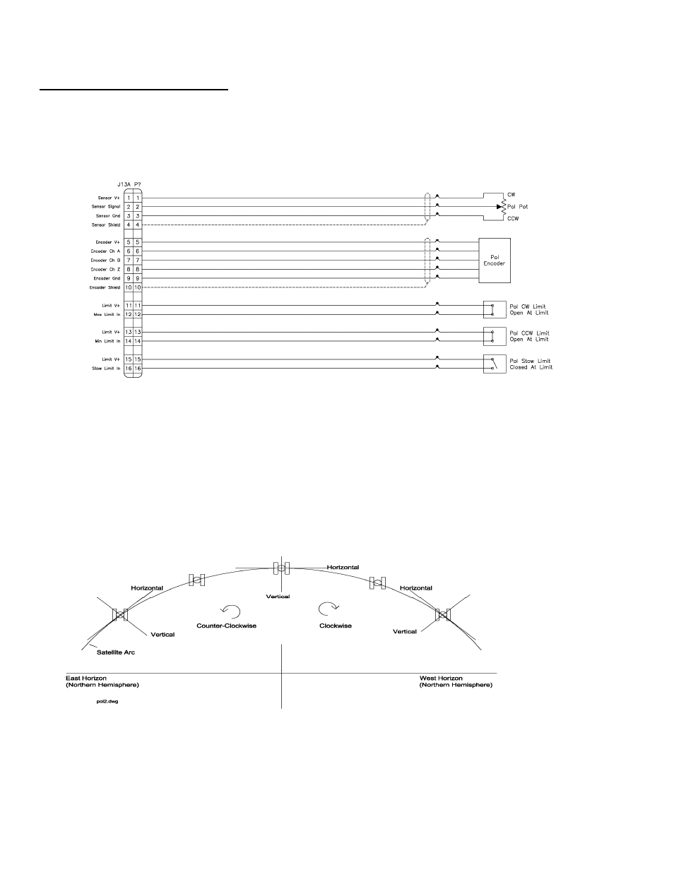
2.1.2.2.13 J13A - Polarization Sensors
J13A "none" 16 pin Type 10
J13 provides a double row of pins. The top 16 pins are designated "J13A" and are typically allocated to
supporting potentiometer, pulse and limit switch feedback from the polarization axis.
The directional sense of polarization movement is defined as CW or CCW, as seen by an observer
standing behind the antenna reflector looking ‘through’ the reflector at the satellite. See diagram below.
The reference position for the polarization position angle is vertical polarization for a satellite located at
the same longitude as the antenna. In the northern hemisphere, for vertically polarized satellites to the
west of the antenna, the polarization deflection is defined as CW relative to the reference position. In the
northern hemisphere, the polarization angle increases for satellites farther to the west. In some modes of
operation the controller predicts the polarization value required to align the antenna with a given satellite’s
horizontal or vertical polarization position. For this feature to function properly the antenna’s polarization
directional sense characteristics (defined by the polarization motor and position sensor) must be
consistent with that of the controller. The following diagram shows the polarization axis sign convention
used. The diagram depicts looking at the arc of satellites from behind the antenna.