Research Concepts RC4000 User Manual
Page 22
RC4000 Antenna Controller
Chapter 2
Hardware
14
2.1.2.1.4 J4 - JTAG
J4 "none" 10 pin Type 4
J4 provides for factory programming of the Drive Board’s microcontroller.
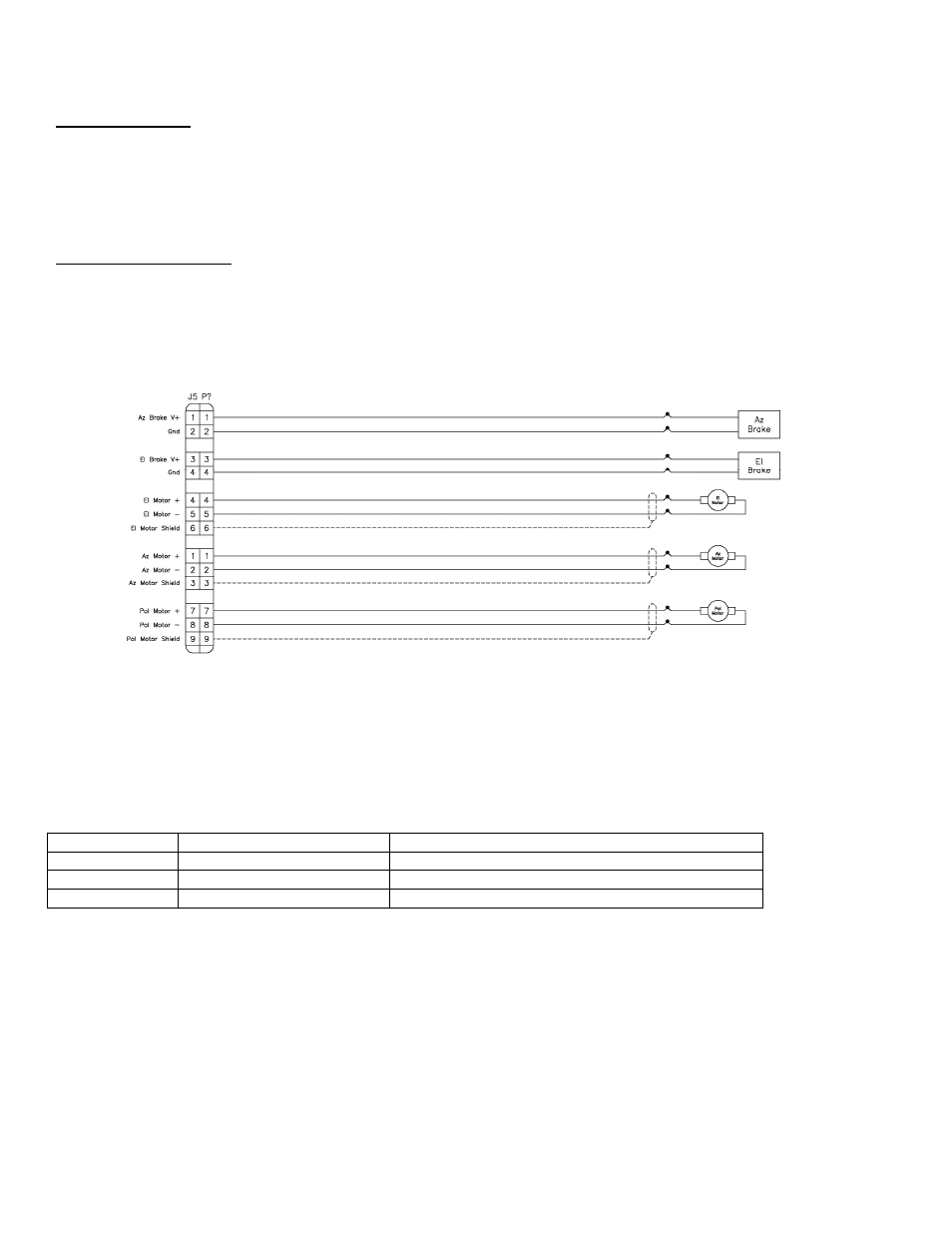
2.1.2.1.5 J5 - Motor Drive
J5 " MOTOR/BRAKES" 13 pin Type 5
-- update pin # per latest schematic (should be # 1 - 13 from top to bottom)
The RC4000 drive section is designed to drive up to 24 volt DC azimuth, elevation, and polarization
motors. The absolute maximum allowed motor current is 12 Amps. The motor drive module supports IR
compensation, current limiting, dual speed operation, and dynamic braking. The drive train is also
protected with resettable fuses.
The following table describes the polarity of the RC4000’s motor drive output signals.
Axis
J5 Terminals
Polarity
Azimuth
5,6
Azimuth CW – 1 has higher potential
Elevation 8,9
Elevation
UP – 4 has higher potential
Polarization
11,12
Polarization CW – 7 has higher potential
-- brake signal pairs (drive capacity, etc.)
-- could be allocated for other functions (fairing drives, etc.)