Super Systems MGA6000 User Manual
Page 11
SSi Manual #4563 Rev. D Page 11 Multi-Gas Model 6000
nitrogen (N2), and 20% carbon monoxide (CO). In many situations, the measured amount of CO is less
than the theoretically exact 20%. This can be due to a variety of factors including seasonal changes in
natural gas composition and incomplete gas cracking in an endothermic generator. The CO Factor and
Process Factor adjustments are intended to make adjustments to the calculation to accommodate differences
between theoretical and actual gas compositions.
Suggested COF / PF
Between the two methods of determining % carbon (probe and infrared), the infrared is considered to be
more accurate. This is because the infrared analyzer evaluates the levels of three gases (CO, CO2, and CH4)
to make its calculation, instead of just using % oxygen like the probe does. At the bottom of the middle
display column,
Calculated
, you will see suggested COF and PF values. These values are determined by
making a comparison between where the probe is actually reading and where it should be reading. The
suggested COF and PF values can be entered into your atmosphere controller to make it display the same %
carbon reading as the MGA6000. By performing periodic evaluations with the MGA6000 and making the
suggested modifications to the adjustment factor in the atmosphere controller, the user can be assured that
the continuous source of process data (the probe) is as accurate as possible. Of course, large changes in CO
Factor or Process Factor should be verified by shim stock analysis or other means to confirm the significance
of the change.
Example – The following will show how to set the Operator variables for: furnace temperature of 1500
degrees, probe millivolts of 1000, probe temperature of 1500 degrees, a CO factor of 250, and the
temperature units are Fahrenheit. When the menu screen first displays, the furnace temperature field is
already highlighted. Enter a 1500 and press Enter. Press the down arrow once to highlight the probe
millivolts field. Enter a 1000 and press Enter. Press the down arrow key once to highlight the probe
temperature field. Enter a 1500 and press Enter. Press the down arrow key once to highlight the CO
Factor field. Enter a 250 and press Enter (Note – there will be an asterisk * next to the value entered).
Press the down arrow key twice to highlight the temperature units field. Enter a 0 and press Enter (Note –
the screen will display degrees F).
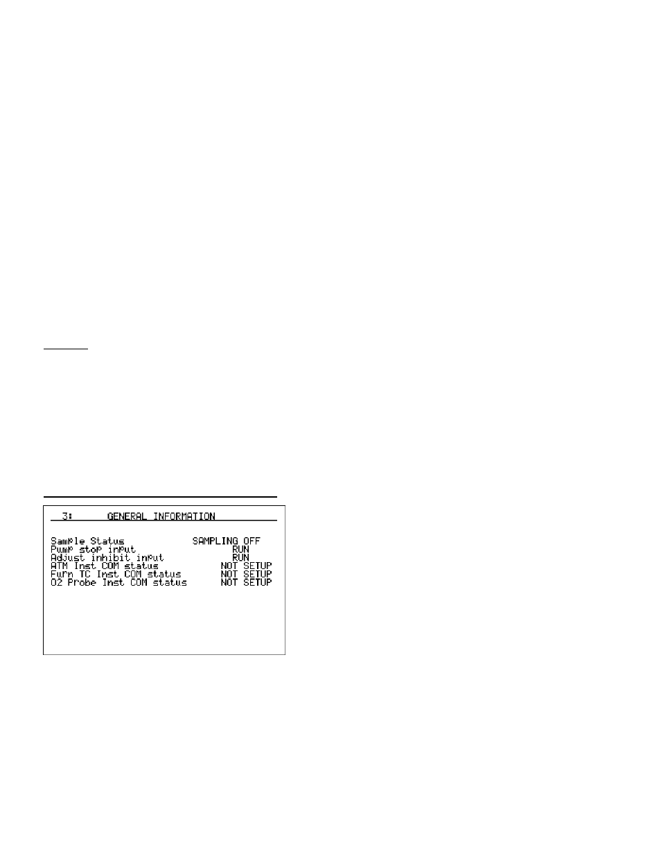
General Information – Menu Page 3
The General Information screen displays some general
information. This screen is for display purposes only, so no
information can be entered on this screen.
There are two digital inputs that can be energized to either
stop the pump or to temporarily inhibit the adjustment of
COF/PF. These can be useful for making sure that the
instrument does not operate normally when unusual
temporary conditions exist (i.e. probe burnoff, door opening,
etc.). Connections for these inputs can be made at the
terminal block (See
Electrical Connections
section). Digital
Input #1 is for stopping the pump. Pump operation will be
stopped if the contact between Terminal 1411 and 1412 is closed. Digital Input #2 is for inhibiting the
adjustment of COF/PF. The adjustment will be stopped if the contact between Terminal 1421 and 1422 is
closed.