Appendix 1 – mga side vents – Super Systems MGA6000 User Manual
Page 27
SSi Manual #4563 Rev. D Page 27 Multi-Gas Model 6000
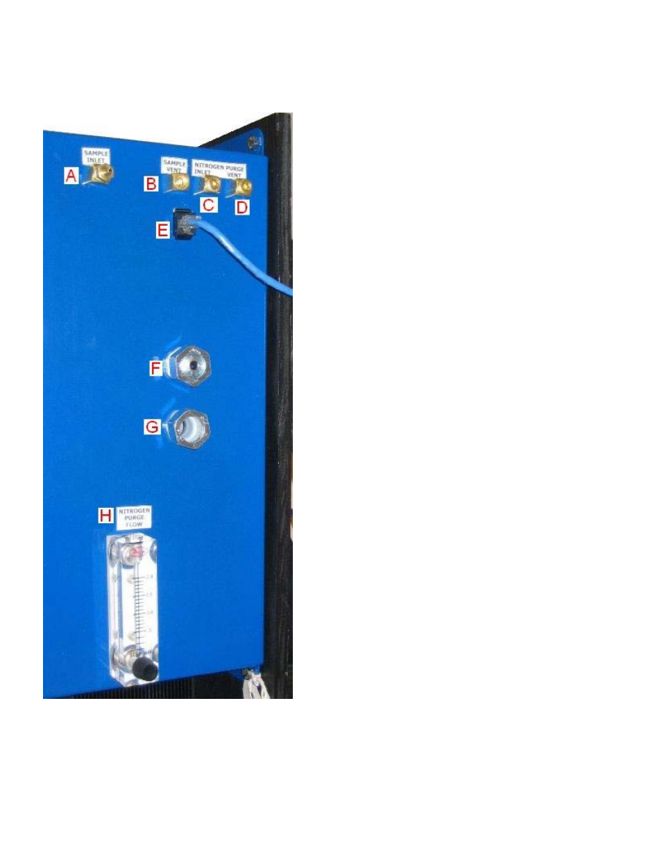
Appendix 1 – MGA Side Vents
A. Sample Inlet – The sample inlet is where the gas
that is being measured goes into the MGA.
B. Sample Vent – The sample vent is where the gas
that is being measured goes out of the MGA after
measurement.
C. Nitrogen Purge Inlet – The nitrogen purge inlet is
where the flow of nitrogen will go into the MGA
during a nitrogen purge. A nitrogen purge will allow
the operator to fill the casing with nitrogen in the
event there is a leak in the gas line.
D. Nitrogen Purge Vent – The nitrogen purge vent is
where the flow of nitrogen will go out of the MGA
when the nitrogen purge is complete.
E. Ethernet Connection – The Ethernet connection is
where the Ethernet wire will be plugged into the
MGA for Ethernet/network communications.
F. Communications Connection – The communications
connection is where the communication wires will
go into the MGA enclosure. Communications could
be: Modbus RS485 communications to an
atmosphere/temperature controller, 4-20 mA
outputs for up to four process variables, digital
inputs to remotely turn the pump off or suspend the
COF/PF adjustment, or communications with the
auto calibration box (if available).
G. Power Connection – The power connection is where
the A/C power wires will go into the MGA enclosure.
The power and communications wires are kept
separate to reduce the possibility of the A/C wires
causing interference with the communications wires.
H. Nitrogen Purge Flow – The nitrogen purge flow
meter will display the flow of nitrogen into the MGA
enclosure during a nitrogen purge.