Connecting the cable, Connecting a ce3/ct3 interface cable, Appearance of the e3/t3 cable – H3C Technologies H3C SR6600-X User Manual
Page 74
66
NOTE:
•
When connecting the interface cable, pay attention to the mark on the interface to avoid wrong
insertion, which might damage the interface module or even the host.
•
H3C recommends that you install a special lightning arrester at the input end of its connection cable to
obtain better lightning protection when the cable is led outdoors. For more information about lightning
arrestor, see the installation guide.
Connecting the cable
1.
Plug the DB-68 end of the 4T1/8T1 splitter cable to the DB-68 interface of the
MIM-8T1/MIM-8T1-F/MIM-IMA-4T1.
2.
Plug the RJ-45 end of the 4T1/8T1 splitter cable to the peer device.
3.
Examine the LINK LED on the MIM-8T1/MIM-8T1-F/MIM-IMA-4T1 after connection. If the LED is
off, a fault has occurred on the link. In this case, examine the link.
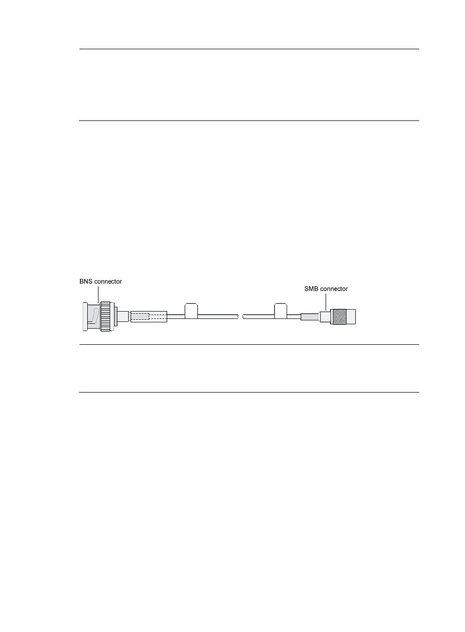
Connecting a CE3/CT3 interface cable
Appearance of the E3/T3 cable
Figure 50 E3/T3 cable
NOTE:
H3C recommends that you install a special lightning arrester at the input end of its connection cable to
obtain better lightning protection when the cable is led outdoors. For more information about lightning
arrestor, see the installation guide.
Connecting the cable
1.
Connect the SMB connector of an E3/T3 cable to the Tx port on the interface module and another
end to the Rx port on the device to be connected.
2.
Connect the SMB connector of another E3/T3 cable to the Rx port of interface module and another
end to the Tx port on the device to be connected.
3.
Examine the LINK LED on the module panel. It is off when fault has occurred on the link and signal
is out of synchronization. In this case, examine the link.