Audio configuration dialog box, output mapping tab – Grass Valley PROFILE FAMILY v.2.5 User Manual
Page 94
Chapter 2
Using the Profile Configuration Manager
94
Profile Family
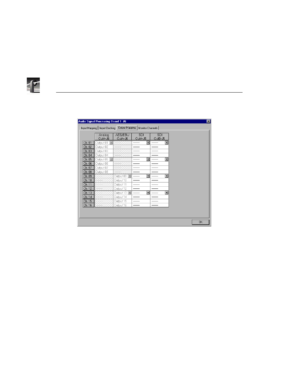
Figure 41. Audio Configuration dialog box, Output Mapping tab
The columns represent the sources to the sixteen channels on the input side and
the destinations from the sixteen channels on the output side. The examples in
Figure 40 and Figure 41 illustrate the system with a PAC 208 chassis allowing
the selection of analog channels 1–8 and digital channels 9–16. A PAC 216
chassis, however, provides sixteen analog inputs and outputs or sixteen digital
inputs and outputs. For the PAC 208, rows 9 through 16 of the analog channel
column, and rows 1 through 8 of the AES/EBU channel column, are cross-
hatched to indicate that these channels are not selectable. In Figure 41, in the
column labeled AES/EBU, rows 9–16 appear dimmed, indicating that this
audio type is always mapped and cannot be unmapped. Attempting to remap
this section results in an error message.
The number of columns in the mapping grid depends on the number of possible
input or output audio types that may be mapped to or from the disk recorder
channels. The grid is used for selecting which of the possible input or output
audio sources and destinations to map to the channels. Audio channels are
mapped in groups of four channels only, and the four audio channels are always
mapped to consecutive disk channels. For example, analog channels 1–4 (Input
01–Input 04) in the first column of Figure 40 are mapped to the first four disk