Mounting a bezel, System connections – Rosen Aviation 19-55 : Remote electronics User Manual
Page 10
Rosen Aviation
Remote Display System
Document Number: 105478
Revision: F
Date: 06/23/14
Template: 4.4.1.6FM2; Revision A; 12/06/12
Page 10 of 38
4.3. Mounting a Bezel
Mount the cosmetic back and monitor before attaching the bezel. To attach a bezel to an RDM,
align the mounting bosses with the monitor standoffs and gently press on the retaining clips to
snap the bezel into place.
Bezels attach around the perimeter of the RDMs with retention fasteners. The quantity and type
of bezel fasteners varies depending on the size of the bezel and RDM. Figure 6 shows the
different assembled retention fasteners on the bezels. See the 55” Bezel Drawing (P/N 5501-
900
) for assembly instructions.
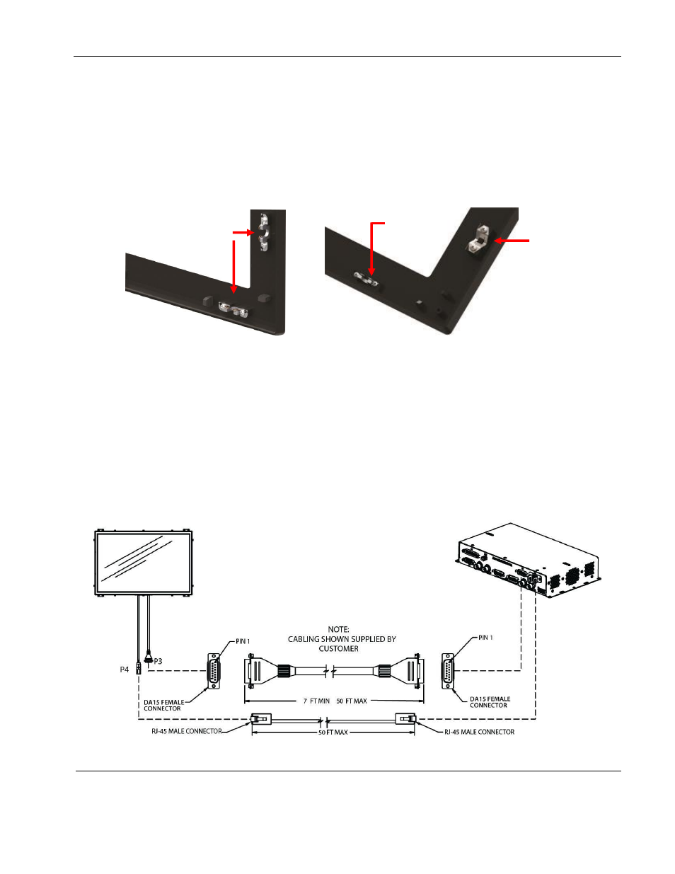
Figure 6 Different bezel retention fasteners
5. SYSTEM CONNECTIONS
The RDM receives power, control, and serialized video from the RMEB located up to 50 feet away,
as shown below. The RMEB outputs a serialized video signal via an RJ-45 cable from P4 and
provides conditioned power and control to the RDM via a harness with DA15 connectors from P3.
To obtain information about interconnect cables, please contact Rosen Aviation’s Technical
Support at 541.434.4512 and request the Interconnect Cable Specification for Remote Electronics
(P/N 105821).
Figure 7 Remote display system connections
Ball stud
receivers on
32”–55”
”
bezels
Only wire
retaining clips on
19”–
26” bezels
Top and
bottom
wire clips