Pinout connections, Rs-232 and rs-485 control inputs – Rosen Aviation 19-55 : Remote electronics User Manual
Page 11
Rosen Aviation
Remote Display System
Document Number: 105478
Revision: F
Date: 06/23/14
Template: 4.4.1.6FM2; Revision A; 12/06/12
Page 11 of 38
5.1. Pinout Connections
There are several ways to connect the remote display system to an aircraft’s entertainment
system.
Follow the pinout descriptions on the technical drawings to assist in completing the wiring
connections. Use the pinout information in the RS-485 Configuration Discretes table on the
technical drawing (P/N 0700-107-CD) when operating in Auto SDI mode.
Note:
This display is for entertainment purposes only; connect to a non-critical power bus.
6. RS-232 AND RS-485 CONTROL INPUTS
Inputs that control the RDMs can come from an IR or via a cabin management system using
RS-232 or RS-485. The RMEB accepts the following commands:
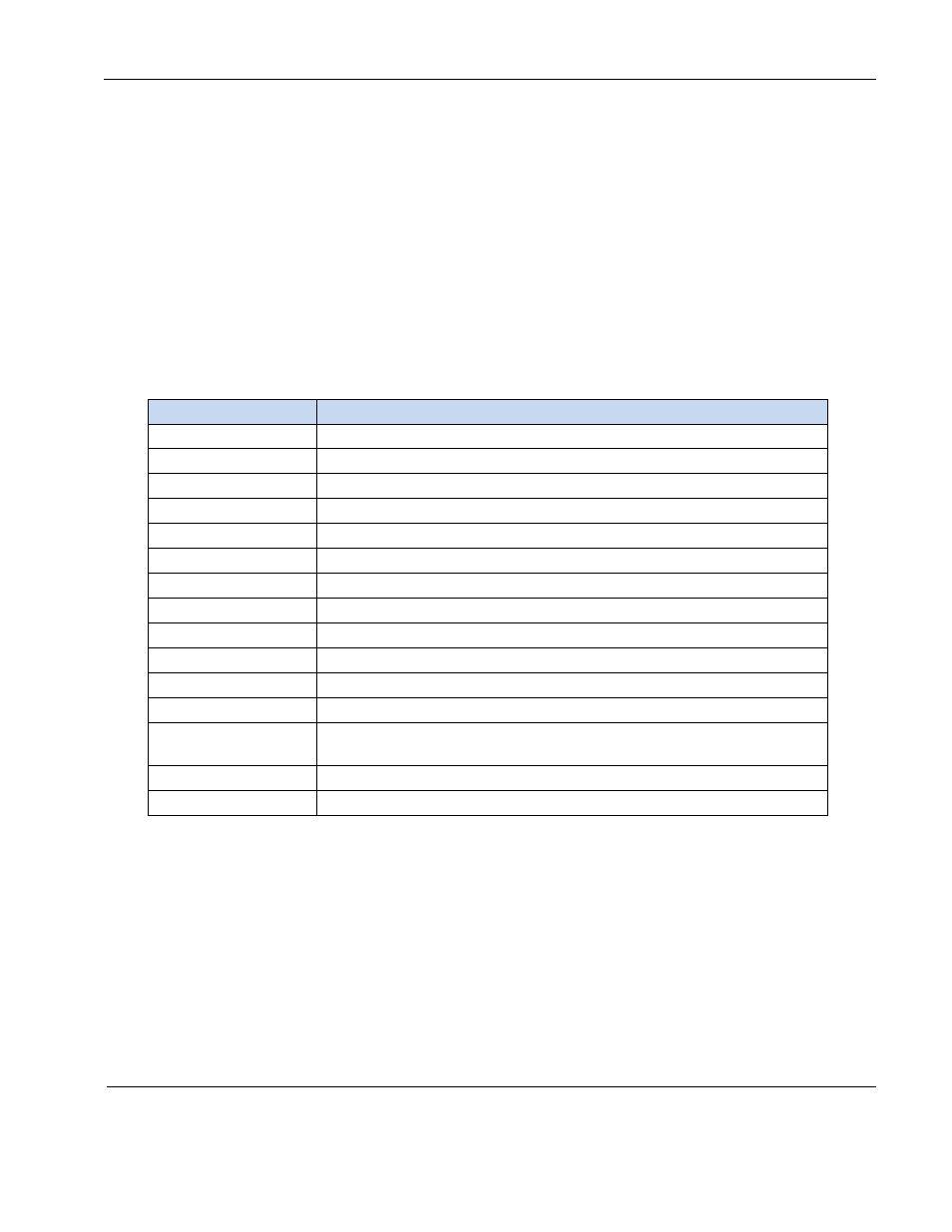
Table 1 RS-485 and RS-232 commands
Control
Description
Power ON
Turn the display on
Power OFF
Turn the display off
Source Composite 1
Select composite 1 video input
Source Composite 2
Select composite 2 video input
Source HD-SDI 1
Select HD-SDI 1 video input
Source HD-SDI 2
Select HD-SDI 2 video input
Source VGA 1
Select analog VGA 1 video input
Source VGA 2
Select analog VGA 2 video input
Source DVI 1
Select DVI 1 video input
Source DVI 2
Select DVI 2 video input
Source YPbPr 1
Select YPbPr 1 component video input
Source YPbPr 2
Select YPbPr 2 component video input
Ping Address
(RS-485 only)
Used by master device to detect all devices attached to the network
Exit
Exit the menu
OK/Enter
Selects active option when OSD is active