Introduction, System overview – Rosen Aviation 19-55 : Remote electronics User Manual
Page 5
Rosen Aviation
Remote Display System
Document Number: 105478
Revision: F
Date: 06/23/14
Template: 4.4.1.6FM2; Revision A; 12/06/12
Page 5 of 38
1. INTRODUCTION
Rosen’s Remote Display System consists of an ultra
-thin remote display module (RDM) and a
high-definition (HD) remote electronics box. The remote electronics design provides more
mounting flexibility because the video processing electronics box can be located up to 50 feet from
the display. The high-definition display modules are available in a range of screen sizes and the
mounting options allow customers to configure a system that fits their aircraft’s cabin interior.
This manual provides general instructions about how to install all bulkhead configurations of the
Remote Display System onto your aircraft. It contains everything you need to know to wire the
components and confirm that the system is functioning correctly.
Note:
Only trained and qualified personnel should perform installation and service.
1.1. System Overview
The Remote Monitor Electronics Box (RMEB) takes a video signal from various sources and
converts it to a serial format for distribution to a high-definition display. The RMEB operates one
Remote Display Module (RDM)—the RMEB 0700-107 Mod 02 is the latest model, which
replaces the RMEB 0700-104, and it operates all RDM sizes currently available from Rosen.
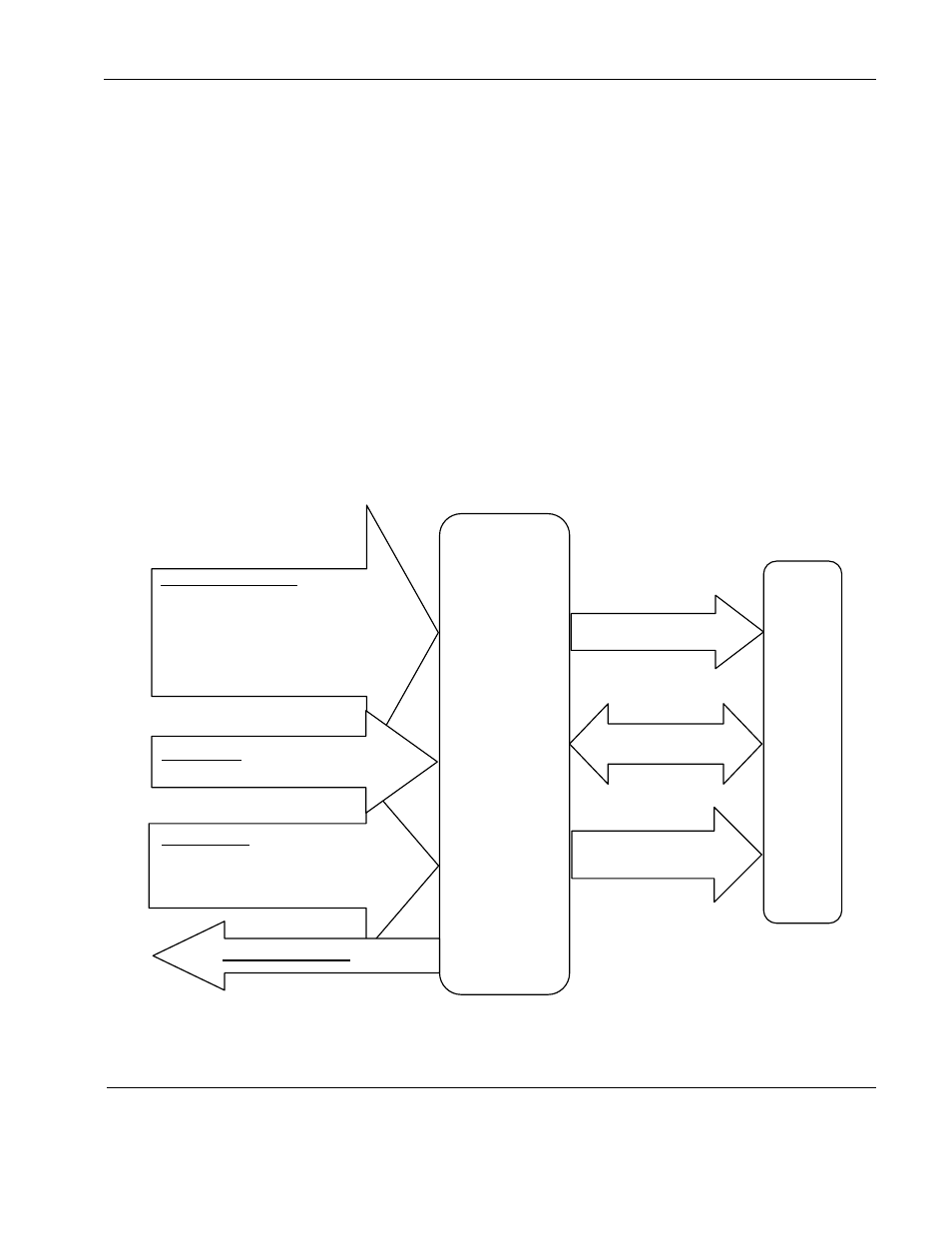
Figure 1 RMEB and RDM functional diagram
Control Input
Wired RS-232 Control
Wired RS-485 Control
Wired Remote IR Receiver
Graphic Signal Input
2x Composite video
2x 3G HD-SDI
2x DVI-I
- for DVI/HDMI w/ HDCP
- for VGA graphics
- for Component video
Remote
Monitor
Electronics
Box
(RMEB)
Power Output
Monitor RS-232
Serialized Video
Output
Power Input
28VDC only
Remot
e Displa
y Mo
du
le (RD
M
)
Status Output & 5V