3 stator, 4 rotor assembly, Stator – Subaru Robin RGD3300H User Manual
Page 23: Rotor assembly
– 20 –
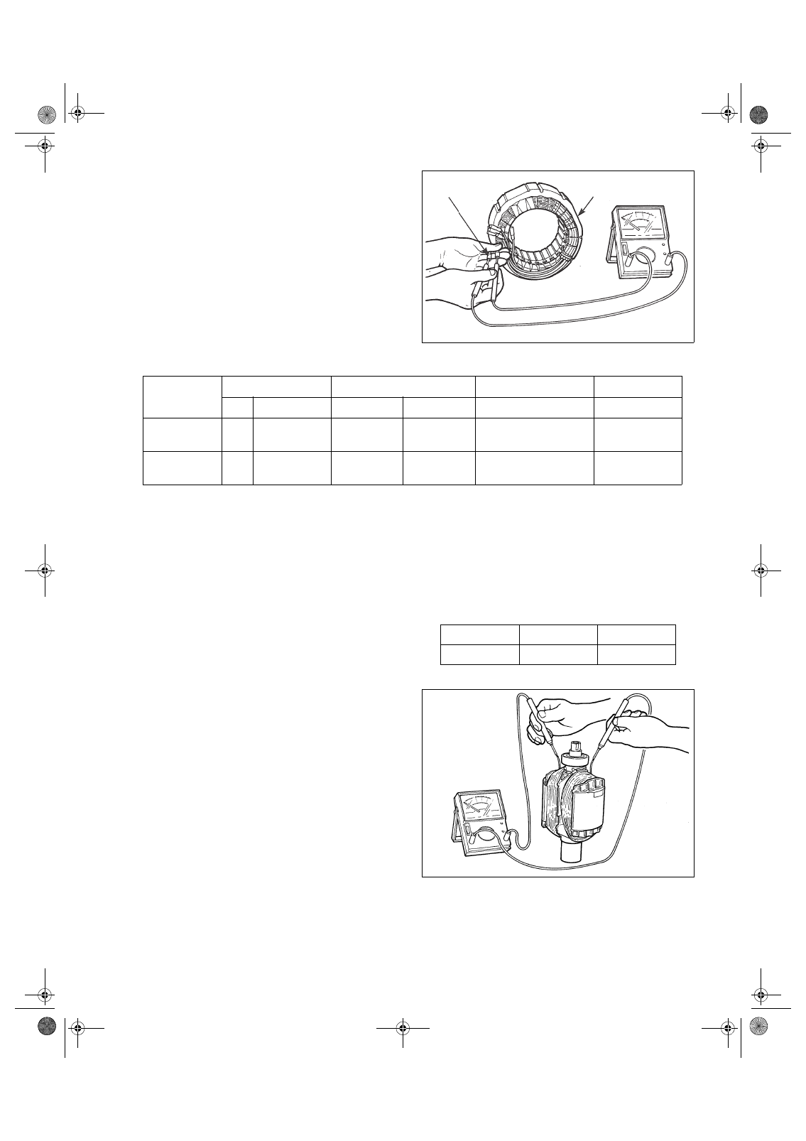
8-3 STATOR
Disengage connectors on the wires from stator and
check the resistance between wires with a circuit
tester referring to the following table.
(R × 1
Ω ±10%)
NOTE: If the circuit tester is not sufficiently accurate, it may not show the values given and may
give erroneous readings.
Erroneous readings will also occur when there is a wide variation of resistance among coil
windings or when measurement is performed at ambient temperatures different from 20°C
(68°F).
8-4 ROTOR ASSEMBLY
(1)
Using the circuit tester, measure the resis-
tance of the field coil.
NOTE 1: Measure the resistance of each coil
winding while the diode and each
resistor are disconnected with their
solder removed.
NOTE 2: If the circuit tester is not sufficiently
accurate, it may not show the values
given and may give erroneous read-
ings.
Erroneous reading will also occur
when there is a wide variation of resis-
tance among coil windings or when
measurement is performed at ambient
temperatures different from 20°C
(68°F).
MODEL
SPECIFICATION
AC Winding
Condenser Winding
DC Winding
Hz
Voltage
White-Red
Black-Blue
Yellow-Yellow
Brown-Brown
RGD3300H
60
120 V
120 V/240 V
0.48
0.48
0.92
0.17
RGD5000H
60
240 V
120 V/240 V
0.23
0.23
0.54
0.13
STATOR
COUPLER
(R × 1
Ω ±10%)
MODEL
RGD3300H
RGD5000H
Resistance
2.1
Ω
1.6
Ω
GENERATOR_GS2380.fm 20 ページ 2007年10月1日 月曜日 午前9時13分