4-6 control box – Subaru Robin RGD3300H User Manual
Page 42
– 39 –
9-4-6 CONTROL BOX
Mount the control box assembly to the frame.
Refer to Section 9-5 for disassembly, checking and
reassembly procedures of the control box.
(1)
Attach the 6 ø terminal of the grounding wires
to the rear of the control box.
4 ø nut (brass) ........................... 1 pc.
Tightening torque: 4.9 ~ 5.9 N-m (50 ~ 60
kg-cm, 3.6 ~ 4.3 ft-lb)
(2)
In the case of generator models equipped
with oil sensor, connect the wires to oil pres-
sure switch and solenoid.
• Screw the black/yellow wire to the center
of the oil pressure switch.
• Connect the two blue wires to the solenoid
and clamp the connectors to the side of
speed control unit.
(3)
Connect the wires drawn out from the stator
to the wires from the control box.
NOTE 1: Connect the wires of the same
color.
NOTE 2: On 240 V model, connect one
blue stator lead with a white con-
trol box lead.
NOTE 3: Engage the connectors securely.
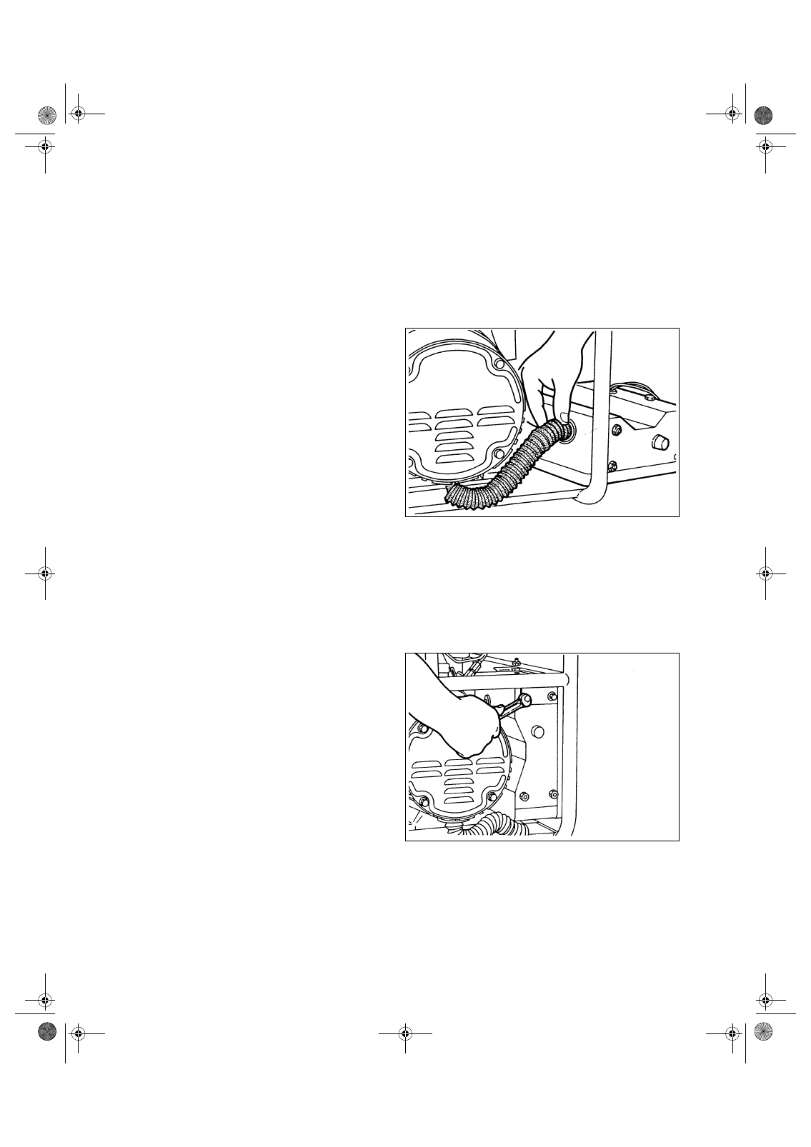
(4)
Push the wires into the control box and attach
the bushing over the wires.
Press the upper end of the bushing into the
control box.
(5)
Install the control box to the frame.
6 ш Ч 16 mm flange bolt ............. 2 pcs.
6 ш Ч 12 mm flange bolt ............. 1 pc.
1 Tighten the above three bolts tentatively.
2 Tighten the two black bolts which join the side
plate to the frame.
3 Tighten the above three bolts adjusting the
position of the control box.
Tightening torque: 4.9 ~ 5.9 N-m (50 ~ 60
kg-cm, 3.6 ~ 4.3 ft-lb)
GENERATOR_GS2380.fm 39 ページ 2007年10月1日 月曜日 午前9時13分