Altera Arria 10 Avalon-ST User Manual
Page 214
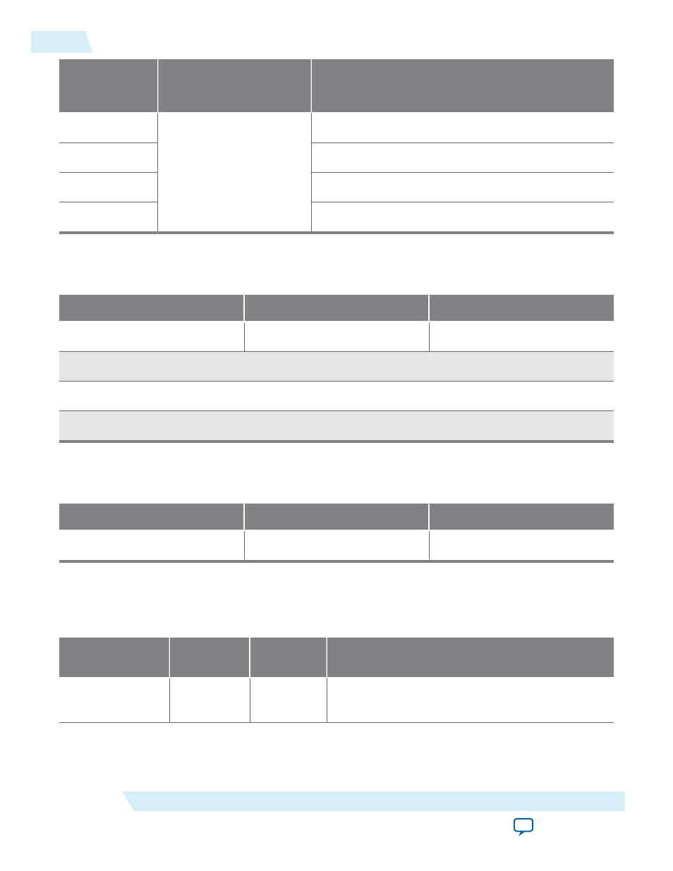
Byte Address
Offset to Base
Source
Descriptor Type
Description
0x ..0
Descriptor <n>
Control fields, DMA length
0x ..4
Endpoint address
0x ..8
RC address upper dword
0x ..C
RC address lower dword
The following table shows the layout of the descriptor fields following the descriptor header.
Table 17-8: Chaining DMA Descriptor Format Map
Bits[31:22]
Bits[21:16]
Bits[15:0]
Reserved
Control Fields (refer to Table 18–9) DMA Length
Endpoint Address
RC Address Upper DWORD
RC Address Lower DWORD
The following table shows the layout of the control fields of the chaining DMA descriptor.
Table 17-9: Chaining DMA Descriptor Format Map (Control Fields)
Bits[21:18]
Bit[17]
Bit[16]
Reserved
EPLAST_ENA
MSI
Each descriptor provides the hardware information on one DMA transfer. The following table describes
each descriptor field.
Table 17-10: Chaining DMA Descriptor Fields
Descriptor Field
Endpoint
Access
RC Access
Description
Endpoint
Address
R
R/W
A 32-bit field that specifies the base address of the
memory transfer on the Endpoint site.
17-14
Chaining DMA Descriptor Tables
UG-01145_avst
2015.05.04
Altera Corporation
Testbench and Design Example