Zilog Z80230 User Manual
Page 159
SCC/ESCC
User Manual
UM010903-0515
Register Descriptions
152
1 Stop Bit/Character (01).
This bit selects Asynchronous mode with one stop bit per character.
1 1/2 Stop Bits/Character (10).
These bits select Asynchronous mode with 1-1/2 stop bits per
character. This mode is not used with the 1X clock mode.
2 Stop Bits/Character (11).
These bits select Asynchronous mode with two stop bits per transmit-
ted character and checks for one received stop bit.
Bit 1: Parity Even//Odd select bit
This bit determines whether parity is checked as even or odd. A 1 programmed here selects even
parity, and a 0 selects odd parity. This bit is ignored if the Parity enable bit is not set.
Bit 0: Parity Enable
When this bit is set, an additional bit position beyond those specified in the bits/character control
is added to the transmitted data and is expected in the receive data. The Received Parity bit is
transferred to the CPU as part of the data unless eight bits per character is selected in the receiver.
Write Register 5 (Transmit Parameters and Controls)
WR5 contains control bits that affect the operation of the transmitter. D2 affects both the transmit-
ter and the receiver. Bit positions for WR5 are displayed in
. On the 85X30 with the
Extended Read option enabled, this register is read as RR5.
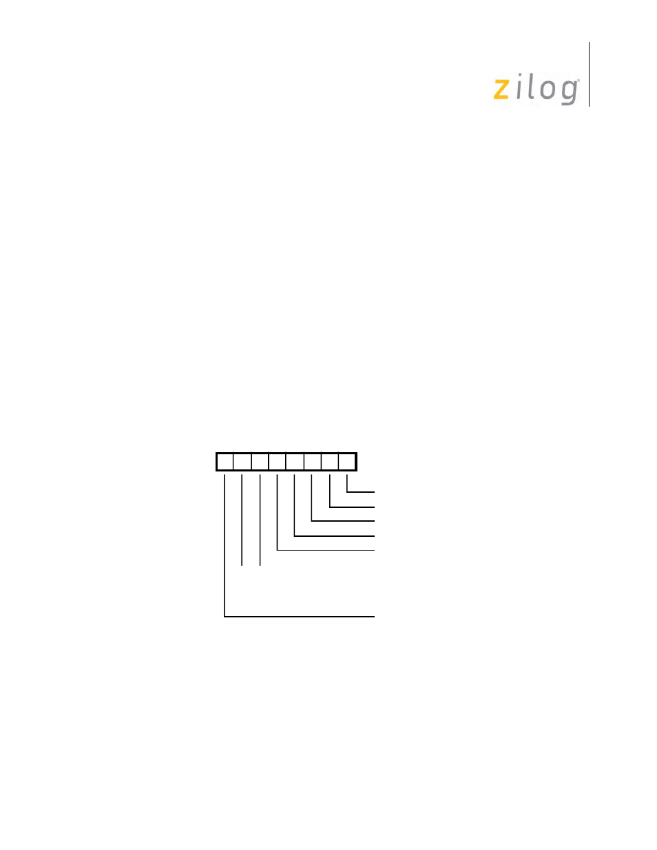
Write Register 5
Bit 7: Data Terminal Ready control bit
This is the control bit for the /DTR//REQ pin while the pin is in the DTR mode (selected in
WR14). When set, /DTR is Low; when reset, /DTR is High. This bit is ignored when /DTR//REQ
is programmed to act as a /REQ pin. This bit is reset by a channel or hardware reset.
Bits 6 and 5: Transmit Bits/Character select bits 1 and 0
D7 D6 D5 D4 D3 D2 D1 D0
Write Register 5
Tx CRC Enable
0 0 Tx 5 Bits(Or Less)/Character
0 1 Tx 7 Bits/Character
1 0 Tx 6 Bits/Character
1 1 Tx 8 Bits/Character
RTS
/SDLC/CRC-16
Tx Enable
Send Break
DTR