Scc/escc user manual – Zilog Z80230 User Manual
Page 97
SCC/ESCC
User Manual
UM010903-0515
Data Communication Modes
90
to enable the Receive FIFO, since it is available in all modes of operation. For each data byte in
the Receive FIFO, a byte is loaded into the Error FIFO to store parity, framing, and other status
information. The Error FIFO is addressed through Read Register 1.
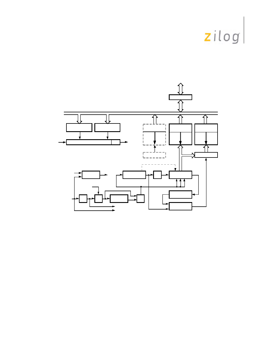
Receive Data Path
Incoming data is routed through one of several paths depending on the mode and character length.
In Asynchronous mode, serial data enters the 3-bit delay if a character length of seven or eight bits
is selected. If a character length of five or six bits is selected, data enters the receive shift register
directly.
In Synchronous modes, the data path is determined by the phase of the receive process currently in
operation. A synchronous receive operation begins with a hunt phase in which a bit pattern that
matches the programmed sync characters (6-,8-, or 16-bit) is searched.
The incoming data then passes through the Sync register and is compared to a sync character
stored in WR6 or WR7 (depending on which mode it is in). The Monosync mode matches the sync
Upper Byte (WR13)
Time Constant
Lower Byte (WR12)
Time Constant
16-Bit Down Counter
DIV 2
Status FIFO
10 x 19 Frame*
BRG
Output
Rec. Data FIFO**
Rec. Error FIFO**
14-Bit Counter
DPLL
DPLL
OUT
Hunt Mode (BISYNC)
Rec. Error Logic
SYNC Register
& Zero Delete
Receive Shift
Register
3-Bit
DPLL
IN
CRC Delay
Register (8 bits)
CRC
Checker
MUX
SYNC
CRC
NRZI Decode
1-Bit
MUX
To Transmit Section
SDLC-CRC
Internal TXD
RxD
CRC Result
I/O Data buffer
CPU I/O
Internal Data Bus
BRG
Input
See
Note
See
Note
See
Note
Notes:
* Not with NMOS.
** Rec. Data FIFO and Rec. Error FIFO are 8 Bytes Deep (ESCC), 3 Bytes Deep (NMOS/CMOS).