Zilog Z80230 User Manual
Page 79
SCC/ESCC
User Manual
UM010903-0515
SCC/ESCC Ancillary Support Circuitry
72
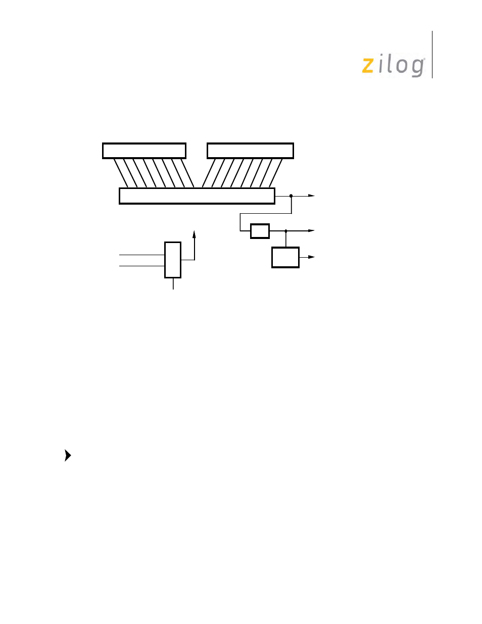
over. The programmed time constant is read from RR12 and RR13. A block diagram of the baud
rate generator is displayed in
.
Baud Rate Generator
The time-constant can be changed at any time, but the new value does not take effect until the next
load of the counter (i.e., after zero count is reached).
No attempt is made to synchronize the loading of a new time-constant with the clock used to drive
the generator. When the time-constant is to be changed, the generator should be stopped first by
writing WR14 D0=0. After loading the new time constant, the BRG can be started again. This
ensures the loading of a correct time constant, but loading does not take place until zero count or a
reset occurs.
If neither the transmit clock nor the receive clock are programmed to come from the /TRxC pin,
the output of the baud rate generator may be made available for external use on the /TRxC pin.
This feature is very useful for diagnostic purposes. By programming the output of the baud
rate generator as output on the /TRxC pin, the BRG is source and time tested, and the pro-
grammed time constant verified.
The clock source for the baud rate generator is selected by bit D1 of WR14. When this bit is set to
0, the BRG uses the signal on the /RTxC pin as its clock, independent of whether the /RTxC pin is
a simple input or part of the crystal oscillator circuit. When this bit is set to 1, the BRG is clocked
by the PCLK. To avoid metastable problems in the counter, this bit should be changed only while
the baud rate generator is disabled, since arbitrarily narrow pulses can be generated at the output of
the multiplexer when it changes status.
Zero
Count
(Gives one Transition
Each Time the Counter
Counts to Zero)
Output
(May Provide
Higher Resolution
to Sample Data)
Desired Baud
(Asynchronous Mode)
Baud Rate
Generator
Clock
(Takes One More
Clock to Load
Time Constant
Value to
Counter
/RTxC Pin
PCLK Pin
16-Bit Counter
WR 13
WR12
÷2
÷Clock
Mode
Note: