3 configuration switch, Configuration switch -8, On 2.2.3) – AMETEK M130 User Manual
Page 26
Sorensen Ethernet Option
2-8
M130/M131 Programming Manual
2.2.3
C
ONFIGURATION
S
WITCH
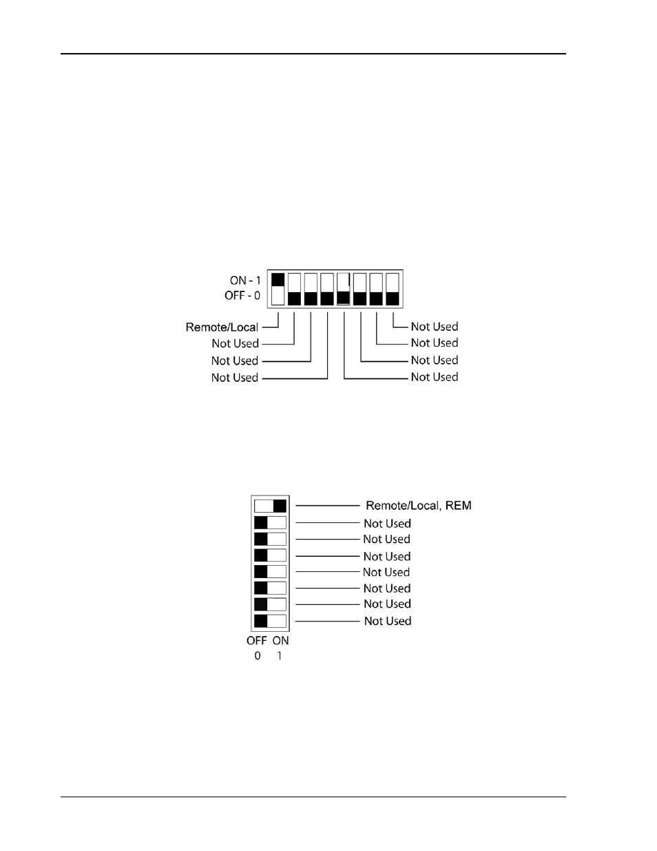
Use the DIP switch, accessible from the rear panel, to configure the power supply
with the installed M130/M131 for the particular system and application in use. The
following figures show the DIP switch configuration for the M130, as set up in
Section 2.1 (see Section 5.2 for the M131).
Note: On the Ethernet master, the rear panel switch gets set to Remote On, and all
remaining switches are disregarded.
Note: Two types of DIP switches are utilized; toggle and rocker. For toggle
switches, the shading indicates the position of the toggle switch. For rocker
switches, the shading indicates the depressed side.
Figure 2-8. DLM 600W Configuration Switch for the M130 Option
Figure 2-9. DCS Configuration Switch for the M130 Option