3 system installation, System installation -3 – AMETEK M130 User Manual
Page 95
Sorensen Ethernet Option
SCPI Status Implementation
M130/M131 Programming Manual
5-3
5.3 S
YSTEM
I
NSTALLATION
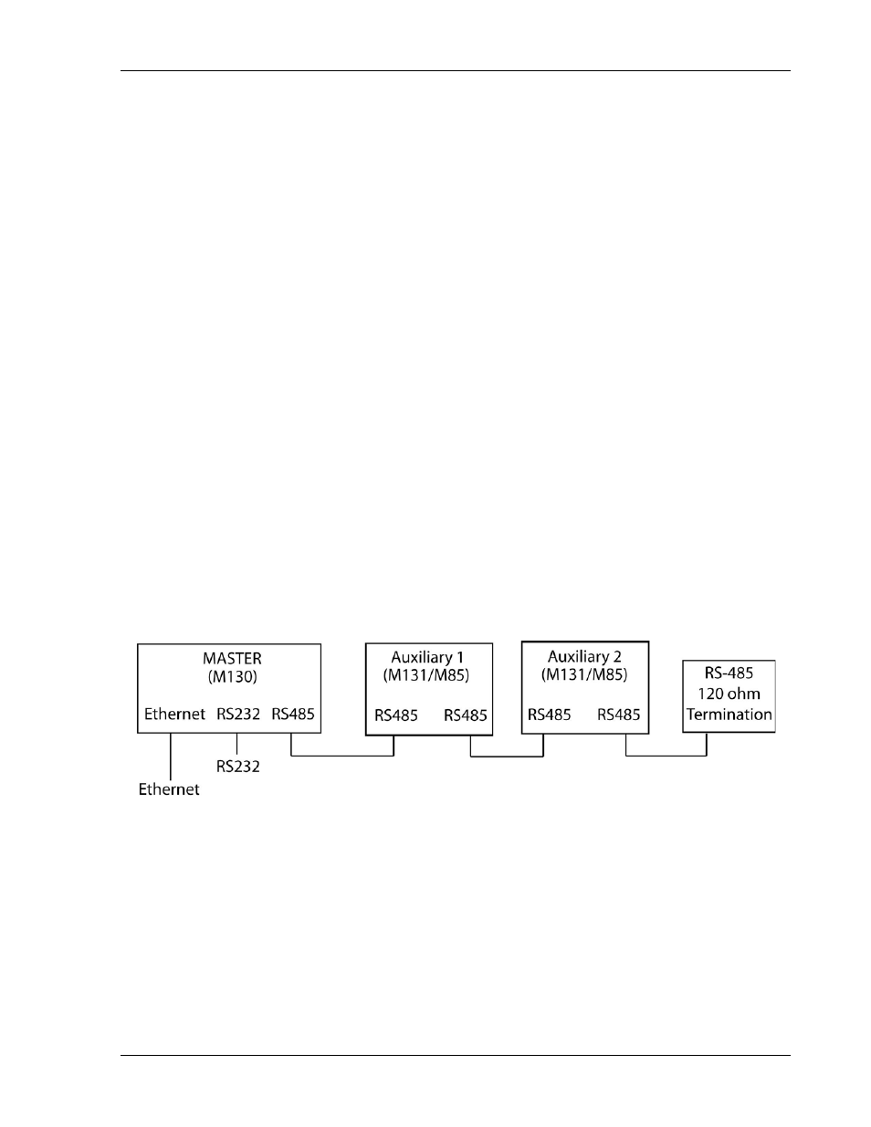
Follow the steps below, illustrated in Figure 5-3, to install the configured M131 into
your system:
1.
Configure the M131 as described in the Configuration section above.
2.
Connect the master unit’s RS-485 output connector, J2, to the auxiliary unit’s
RS-485 input connector, J1, using the modular cable.
3.
If there are additional auxiliary units, connect the installed auxiliary unit’s RS-485
output connector, J2, to the additional auxiliary unit’s RS-485 input connector,
J1, using the modular cable.
4.
Connect the 120 ohm resistive termination assembly to the last auxiliary unit’s J2
connector.
5.
Connect power to the system, power it up, and verify that the green REMOTE
LED on the front panel is ON.
6.
Test the link by communicating with the auxiliary unit from the master unit, using
the *IDN[n]? command. Note that [n] is the channel number—for example,
*IDN2? calls channel 2. (In response to this string, the system returns the power
supply model number and the firmware version.)
NOTE: The slave baud rate is 9600.
Figure 5-3. RS-485 System Interconnection with Two Auxiliaries