Comtech EF Data SFC4200 User Manual
Page 17
SFC4200/SFC1275G Synthesized Frequency Downconverter
Operation
TM054 - Rev. 4.0
3-1
Section 3 - Operation
3.0 Theory of Operation
The SFC Downconverters have been designed to minimize the amount of hardware in the
system while maximizing performance. Spurious performance in the Downconverter is critical
and in particular, LO related spurious In-Band is nonexistent.
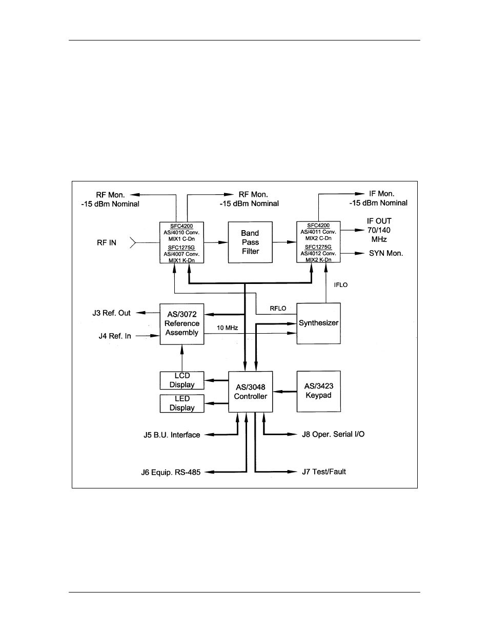
The SFC Downconverters are double conversion microwave Downconverters. The block
diagram (Figure 3-1) of the system includes the Signal RF Assembly, the Synthesizer Assembly,
the Reference Assembly, the Monitor and Control (M&C) Microcontroller, and Power Supply
Subsystem.
Figure 3-1. SFC Downconverter Block Diagram
3.1 Signal RF Assembly
The Signal RF Assembly is a subassembly that holds the first and second mixer converter
modules, and the IF Cavity Filter. The first and second mixer modules for the SFC4200 and
SFC1275G Downconverters are described below.