Comtech EF Data SFC4200 User Manual
Page 26
User Interfaces
SFC4200/SFC1275G Synthesized Frequency Downconverter
4-2
TM054 - Rev. 4.0
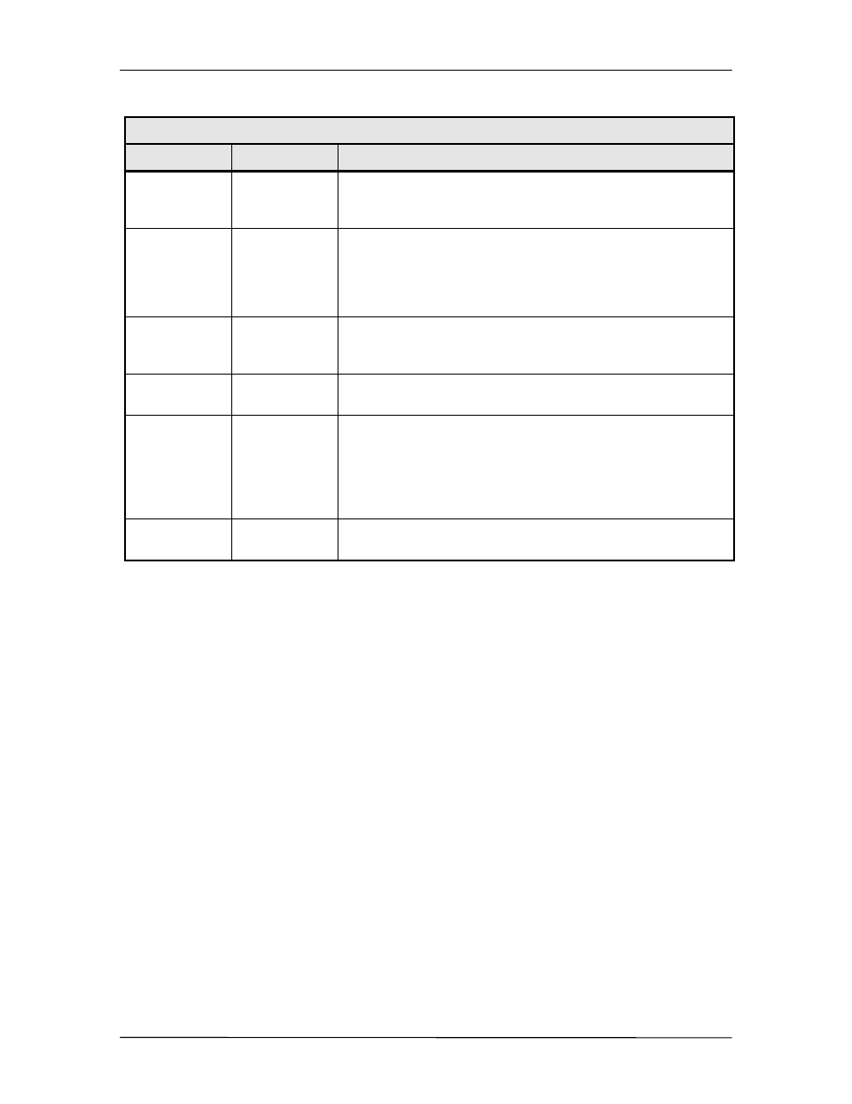
Table 4-2. Front Panel LED Indicators
LED
Color
Function
POWER
Green
Indicates the presence of primary power and that the On/Off
Switch located on the rear of the chassis is in the On
Position.
EXT REF
Green
This LED indicates that an external 10 MHz reference signal
has been applied to the converter. A LO fault may occur
when the external reference is applied or removed. This
indicates that a change in the reference has occurred. This
fault can be cleared with a soft reset.
REMOTE
Green
The Remote LED indicates that the converter has been
addressed via the operator RS-232 Serial Interface, and that
a command has been received.
STANDBY
Yellow
This LED, when illuminated, indicates that the converter is
waiting to be off-line.
LO FAULT
Red
If the Synthesized LO or IFLO System of the converter
indicates an out-of-lock condition, the LO Fault LED will
illuminate. At this time, the Summary Fault Relay Contacts
will latch. If the LO Fault was due to an Intermittent Fault
Condition, the LO Fault will flash at one second intervals,
and fault checked may be reset.
SIG FAULT
Yellow
Signal Faults are used in switch configuration to indicate
switch status (when in the Backup Mode).
4.1.2 Front Panel LCD Display
The front panel display is a 2 line by 24-character LCD display that is capable of displaying five
fields of information in each menu window. While at the Root Menu, the Front Panel LCD
Display displays five fields, which are depicted by text captions around the display bezel. These
fields are listed below. The LCD display is a single entry window into the large matrix of
parameters that can be monitored and set from the front panel.
RX Frequency:
The RX Frequency Field shows the frequency of the
selected input signal that will be converted to
70/140 MHz. When the cursor is placed in the
Frequency Field, and the Converter is in ‘SETUP’ Mode,
the frequency operation can be modified.
STATUS:
The Status Field indicates the Mode of Operation or
Status of the Converter. The Modes of Operation
include ‘SINGLE’, ‘PRIMARY’, ‘BACKUP’, ‘SETUP’, and
‘OFF LINE’. The Single, Primary or Backup Status
indicates that there are no faults. It also identifies the
current configuration of the Converter. The Off Line
Status indicates that the Converter is off line due to a
fault condition.
Note: Because the backup ‘Learns’ the Frequency, Channel and Gain from the Prime,
changes to these fields are not allowed in the Backup converter.