Comtech EF Data SFC4200 User Manual
Page 53
SFC4200/SFC1275G Synthesized Frequency Downconverter
Electrical Interfaces
TM054 - Rev. 4.0
5-3
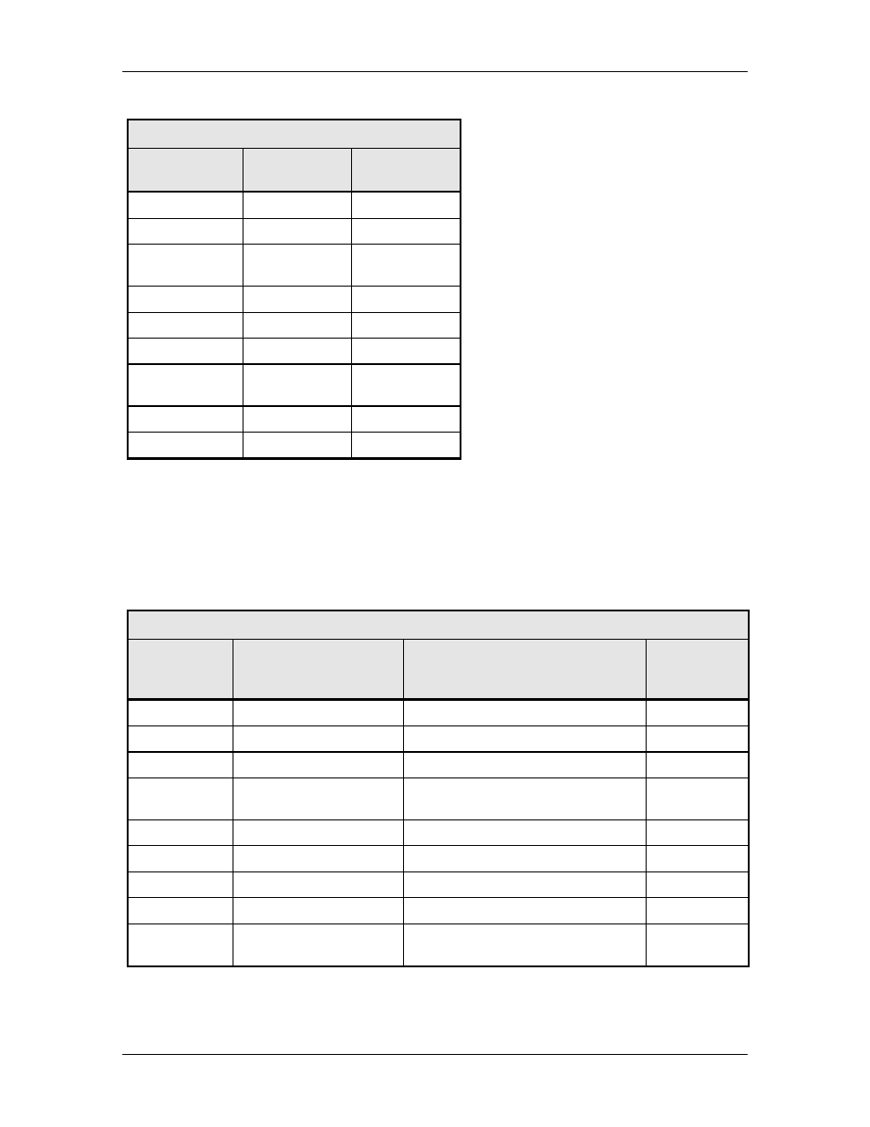
Table 5-2. J6 – Equipment RS-485 Interface
Description
10 Pin
AS/3048 (J14)
1
GND
1
2
SRCLK
3
3
Not
Connected
5
4
Tx Not
7
5
Tx
9
6
SR DAT
2
7
Not
Connected
4
8
Rx Not
6
9
Rx
8
5.8 Test/Fault (J7)
The Test Port/High-Speed Switch Interface (J7) provides a port where all analog voltages used
in determining fault status by the microprocessor are made directly available to the rear panel of
the converter. Synthesizer and signal path faults can be verified with a voltmeter using the
following test points. The pinouts of this connector are listed in Table 5-3.
Table 5-3. J7 – Test/Fault Interface – D-Sub 15-Pin Connector
Pin No.
Signal
Description
Controller
AS/3048 (J5)
A/D Chan.
1
N/C
1
2
LOFLT
Open Collector
3
3
GND
5
4
IFSIGDET
IF Signal Detected Power Level
(0 – 10 VDC)
7
5
N/C
9
6
N/C
2
7
TEMP
N/A
4
8
N/C
6
9
RFSIGDET
RF Signal Power Level Detect
(0 – 10 VDC) (U/C Only)
8