Comtech EF Data SFC4200 User Manual
Page 52
Electrical Interfaces
SFC4200/SFC1275G Synthesized Frequency Downconverter
5-2
TM054 - Rev. 4.0
the individual online converters or the backup unit. This interface finds use in both the 1:1 and
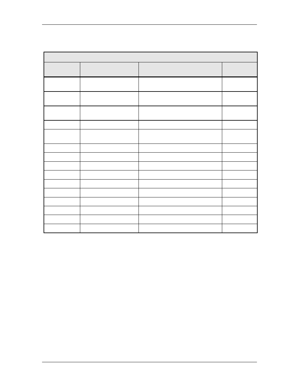
1:N configuration type switches. The pinouts of the switch is listed in Table 5-1.
Table 5-1. J5 – Backup Switch Interface – D Sub 15-Pin Connector
Pin No.
Signal
Description
Controller
AS/3048 (J7)
1
N.O.
Form-C contact summary fault
normally open contact
1
5
N.C.
Form-C contact summary fault
normally closed contact
9
9
COM
Form-C contact summary fault
common contact
2
13
GND
Ground
10
2
+15 V Or’d
Diode Or’d +15 VDC from
converter
3
6
FCB1
Fault Code Bit 1
11
10
FCB2
Fault Code Bit 2
4
14
FCB3
Fault Code Bit 3
12
3
FCB4
Fault Code Bit 4
5
7
IDB1
ID Bit 1
13
11
IDB2
ID Bit 2
6
15
IDB3
ID Bit 3
14
4
IDB4
ID Bit 4
7
8
INT O
Interrupt
15
12
RMT
8
5.7 Equipment RS-485 (J6)
The Equipment Multi-Drop, Full-Duplex, Bi-directional RS-485 Interface (J6) allows
communication between converters. Because the RS-485 Interface uses a master/slave
(talker/listener) configuration, the converter that is designated as the backup will automatically be
established as the master. Under normal RS-485 protocol, the master will poll a specific slave
by address and only then will the slave unit respond. The swapping of Transmit Data and
Receive Data is accomplished in the inter-converter cable, as the hardware interface is identical
for all converters. Refer to Table 5-2 for pinouts.