Comtech EF Data SFC4200 User Manual
Page 51
SFC4200/SFC1275G Synthesized Frequency Downconverter
Electrical Interfaces
TM054 - Rev. 4.0
5-1
Section 5 – Electrical Interfaces
5.0 SFC Downconverter Connections
All SFC Downconverter connections are made to labeled connectors. Any connection interfacing
to SFC Downconverters must be the appropriate mating connector. Refer to Figure 5-1 below
for the various connector locations.
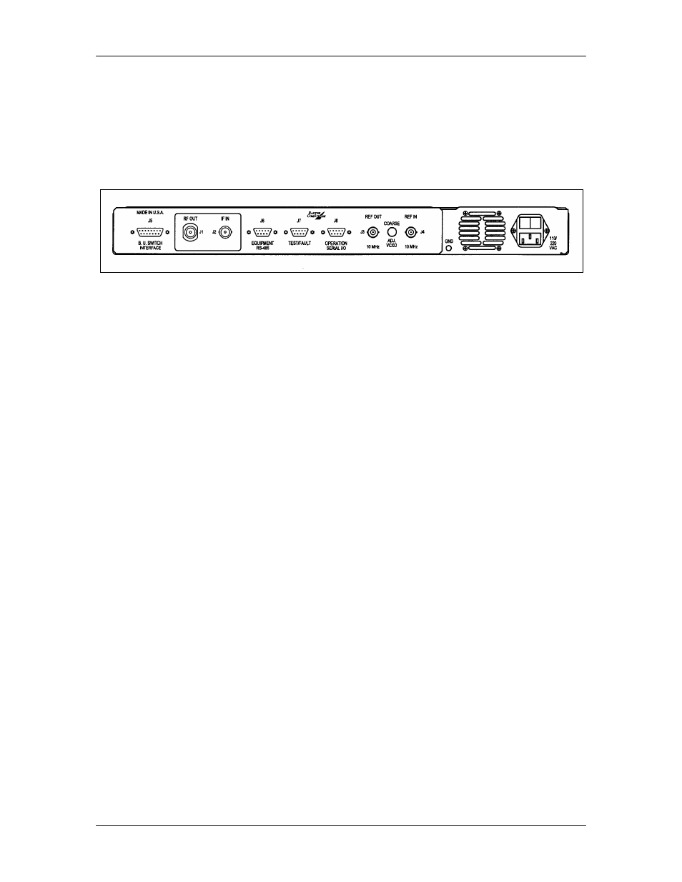
Figure 5-1. SFC Downconverter Rear Panel
5.1 Power
Located on the right-rear side of the SFC Downconverter Rear Panel is the AC Power Input
Connector. This connector is an IEC 320/C13 Power Entry Module. The unit is powered from a
100 – 240 VAC, 50 – 60 Hz source. Maximum unit power consumption is 50 W. The switch
turns power on and off to the unit. A chassis ground connection can be made at the #10 size
stud located to the lower left of the AC Power Connector.
The power cord/connector for the SFC Downconverter is a supplied item.
5.2 RF In (J1)
The RF In (J1) is the Primary RF Input of the SFC Downconverters. It is an N-Type Female
Connector for the SFC4200, and an SMA Female Connector for the SFC1275G.
5.3 IF Out (J2)
The IF Out Connector (J2) is the 75 Ohm BNC-F Connector. Outputs are within 50 – 90 MHz for
standard units and 100 – 180 MHz for units equipped with 140 MHz.
5.4 10 MHz Ref Out (J3)
The 10 MHz Reference Out (J3) is the 50 Ohm BNC-F Connector that provides a 10 MHz
squarewave, 50 Ohm AC coupled reference output signal at 0 dBm. In normal operation (no
external reference) this output is synchronous with the internal high stability 10 MHz reference.
5.5 10 MHz Ref In (J4)
The Reference Input BNC-F connector (J4) at the rear of the converter allows the operator to
synchronize the synthesizer of the converter to an external 10 MHz reference. When an external
reference is properly applied to the reference input, the external reference LED will illuminate on
the front panel.
5.6 B. U. Switch Interface (J5)
The Backup Switch Interface (J5) is a D Sub 15 Pin Connector that connects each converter with
the RCU101 or RCU108 Backup Switch Unit. This cable is not daisy-chained between
converters, but serves as a direct link for each converter in the configuration, whether they are