Comtech EF Data SFC4200 User Manual
Page 42
User Interfaces
SFC4200/SFC1275G Synthesized Frequency Downconverter
4-18
TM054 - Rev. 4.0
Long term stability of the reference is affected by factors other than temperature. Over days and
months, the frequency of the reference will drift at a rate specified as aging. Typical aging rates
of 1 to 5 parts in 10
-10
per day are typical in a crystal that has been stabilized for a few weeks.
The first month of operation for any crystal is a time where drift due to aging can be excessive.
The typical aging curve provides insight into the exponential decay in aging rate for a 10 MHz
Reference. Converters shipped from the factory have had their reference oscillator aged for a
minimum of 30 days and in addition, the aging rate has been verified in the final week to within
tolerance. However, converters that have been in storage or powered off for a period of several
weeks will exhibit a phenomenon whereby the aging curve return to the slope shown for zero
days of aging. This aging reset in not well understood but the manufacturers of crystals believe
it to be related to a gradual relaxation of the molecular makeup of the quartz substrates and the
conductive films deposited on the quartz.
The rule of thumb when checking the frequency accuracy of the converter is to make sure that
the crystal has stabilized before attempting any adjustment. For units that have been in storage
or shipment for more than a week, allow several days of operation before verifying the accuracy.
For this reason, converters shipped from Radyne ComStream Corporation are typically powered-
up until the final day before shipment. In addition, the accuracy and aging rate are verified
immediately prior to shipment.
For a converter that has been powered-up for several months, the operator can assume an aging
rate of several PPB per month. If the aging rate has been established, the station operator can
make calculated adjustments from the reference offset menu at timed intervals.
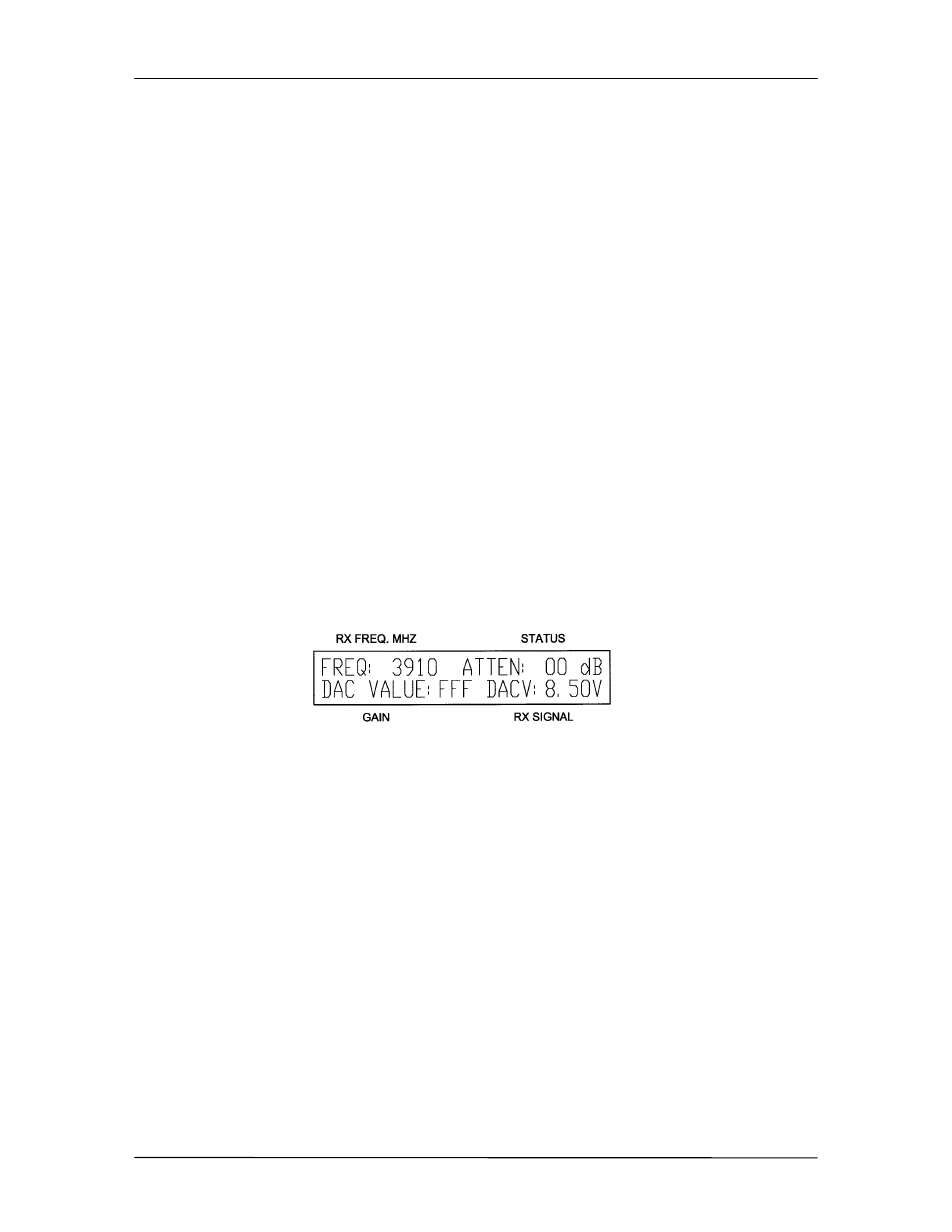
4.2.11 Output Attenuator Calibration Menu (locked, not user accessible)
The Output Attenuator (Figure 4-20) can be calibrated over 0 – 40 dB of attenuation in 1 dB
increments over frequency bands centered 50 MHz apart.
Figure 4-20. Output Attenuator Calibration Menu
Freq:
Shows the 50 MHz Frequency Band that is currently
being calibrated. While in this menu, selecting or
changing a Frequency Cal Band will cause the
synthesizer to change to that center frequency. The
frequency band selection can be incremented or
decremented by placing the cursor on the current
frequency and depressing the Up or Down cursor
buttons.
Atten:
This number, located under the Status Field
nomenclature, indicates the location for or value of
attenuation for which the operator is calibrating the
Digital-to-Analog Converter (DAC) Value. The Atten
value can be increased by depressing <ENTER>.
When <ENTER> is depressed, the DAC Value displayed
is stored into non-volatile memory and the Atten digit is
increased to the next value. At 20, this digit rolls over to
0.