Comtech EF Data SFC4200 User Manual
Page 25
SFC4200/SFC1275G Synthesized Frequency Downconverter
User Interfaces
TM054 - Rev. 4.0
4-1
Section 4 – User Interfaces
4.0 User Interfaces
The Front Panel may be used to monitor and control the SFC Downconverters.
4.1 Front Panel User Interface
The Front Panel of the SFC Downconverters allows for complete M&C (including but not limited
to operation, calibration, and testing) of all parameters and functions via a Keypad, LCD Display
and Status LEDs.
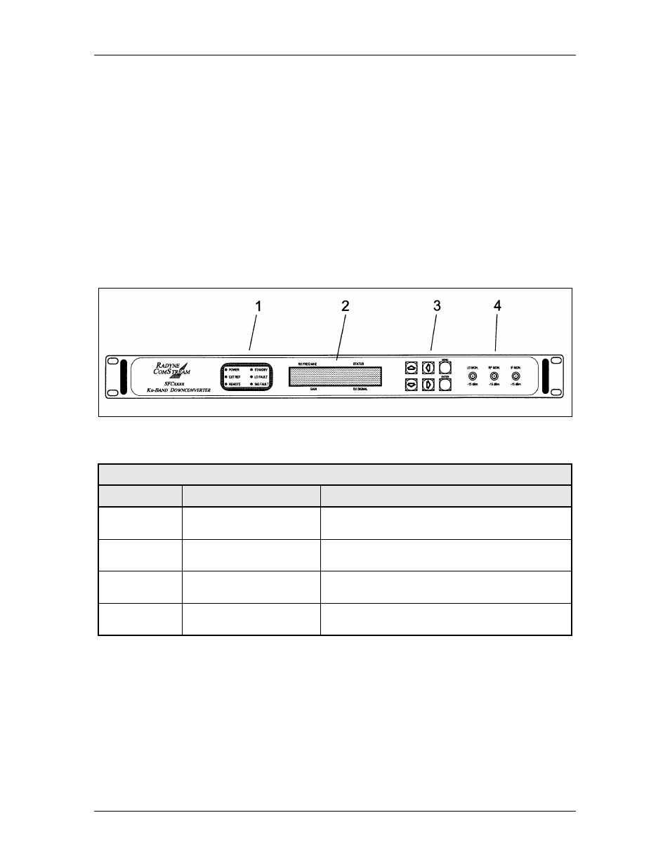
The front panel layout is shown in Figure 4-1, showing the location and labeling of the front
panel. The front panel is divided into four functional areas: Front Panel LED Indicators, Front
Panel LCD Display, Front Panel Keypad, and Monitoring Ports, each described in Table 4-1.
Figure 4-1. SFC Downconverters Front Panel Controls and Indicators
Table 4-1. Front Panel User Interface
Item No.
Description
Function
1
Front Panel LED
Indicators
Refer to Section 4.1.1 for an itemized description
of these LEDs.
2
Front Panel LCD Display
Displays SFC Downconverter operating
parameters and configuration data.
3
Front Panel Keypad
Controls the up, down, left, and right movement
of the cursor in the Front Panel LCD Display.
4
Monitoring Ports
Allows the monitoring of the LO, and RF and IF
Signals.
4.1.1 Front Panel LED Indicators
There are six LEDs on the SFC Downconverter Front Panel to indicate the operation status
(Table 4-2). The LED colors maintain a consistent meaning. Green signifies that the indication
is appropriate for normal operation, Yellow indicates operation status, and Red indicates a fault
condition that will result in lost communications.