Worcester controls – Flowserve I90 Series User Manual
Page 10
10
Pulsair Loop-Powered Positioner Modular Accessory System (Series I90/L90)
WCAIM2053
procedure again. If the unit will still not calibrate,
then there could be a problem with the
potentiometer, wiring, or positioner board.
10. Press and hold the “FUNCT” button until the display
stops flashing (about 5 seconds). The display will
now show a readout of valve position in percent open.
The unit cannot be operated remotely with the 4-20
mA signal when the position is indicated on the
display. Momentarily press the “FUNCT” button to
clear the display and enable remote operation. The
actuator should immediately move to the position
dictated by the input signal. The valve position can be
checked at any time by pressing the “FUNCT” button.
When the display is set to indicate valve position, the
“UP” and “DOWN” buttons can be used to position
the actuator to any desired position:
• “UP” causes the actuator to rotate in the
CCW direction
• “DOWN” causes the actuator to rotate in the
CW direction.
Be certain to clear the display when finished to allow
remote operation of the valve.
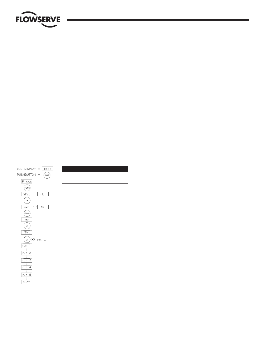
SELF-CALIBRATION FLOWCHART
OPERATION OCCURRING IN
POSITIONER
init non manual mode (actuator 25% to
75% open to start)
Configuring first position
Configuring second position
Self-calibration has not been completed
START OF SELF-CALIBRATION
Determine the direction of action
Control of actuator travel; scaling of zero
point and stroke to the setpoint range
Determine up and down actuating times;
displayed alternately in seconds
Determine the minimum positioning
increments
Optimize transient response
END OF SELF-CALIBRATION
IMPORTANT: The feedback potentiometer (“A” potentiometer, if dual
pot is installed) is now calibrated for only one 90 degree quadrant of
valve operation. If the output shaft is repositioned to another 90
degree quadrant or if the output shaft is rotated a multiple of 360
degrees from its original position or if the M.A.S. package is removed
from the actuator, the feedback potentiometer will no longer be in
calibration and the positioner must be recalibrated as directed.
5. RECALIBRATION OF POSITIONER
If the positioner needs to be recalibrated for any reason, such
as the installation of a new feedback potentiometer, use one
of the following two procedures:
a. If it is desired to restore the factory settings as well as
recalibrate the positioner, then use the “PrSt” function
from the selection menu. This function is known as the
factory preset function. the “FUNCT” button until the
display begins flashing then press the “DOWN” button
momentarily to get “PrSt” flashing on the display.
Momentarily press the “FUNCT” button. The display
should now show a continuous “no” or “oCAY”. “no”
means that not all of the functions are set to the factory
presets. “oCAY” means that they are set to factory
presets. If the display shows “no”, then press the “UP”
button and “Strt” will begin flashing on the display, and
then shortly thereafter “oCAY” will begin flashing. When
this happens, the factory presets are loaded.
b. If it is desired to recalibrate the positioner without
changing any of the functions, then use the “init” function
from the selection menu. Perform steps 1 through 9 of
the calibration procedure outlined in Section III.A.4.c until
“run1” appears in the display. Immediately turn off (or
disconnect) the loop power. The display will go blank.
When the power is restored, the display will show a letter
“P” and a position number from 0 to 99. This indicates
that the positioner is no longer calibrated. You may now
proceed to adjust the potentiometer and calibrate the
positioner as outlined in steps 1 through 10 of the
calibration procedure (section III.A.4.c).
6. OPERATING FUNCTION SETTINGS
a. Changing function settings
The loop-powered positioner board has a number of
functions that can be programmed into memory after the
circuit board has been calibrated. Following is a list of
these functions, a short explanation of each, and how
they are entered into memory. The letters at the beginning
of each explanation are those that will appear in the
display window when that function is selected with the
function button (labeled “FUNCT”). These changes all take
place in the manual mode. To get to any particular
function on the digital display, press and hold the
“FUNCT” button until the display begins flashing between
“YFct” and its current setting (“Lin” or “nLin”). Quickly
press and release the “FUNCT” button and the display will
lock on the current setting (it will still be flashing). Use
the “UP” or “DOWN” buttons to change the setting. To go
to the next function, quickly press and release the
“FUNCT” button. The display should again begin flashing
between the selected function and its current setting. Now
quickly pressing the “UP” or the “DOWN” button will
move to the next function. Continue pressing and
releasing the button until the desired function appears.
b. Function Descriptions (Refer to table in Section III.A.3.b.)
Flow Control Division
Worcester Controls