Worcester controls – Flowserve I90 Series User Manual
Page 5
WCAIM2053
Pulsair Loop-Powered Positioner Modular Accessory System (Series I90/L90)
5
B. AIR CONNECTIONS
IMPORTANT: Use industrial air (or other non-corrosive gas),
which must be dry and oil-free. See section lll.C on page 15 for
other air supply requirements and technical data.
1. Series I90/L90 mounting kits contain two (2) elbow “quick”
fittings, two (2) straight “quick” fittings, and one (1) length of
Z|v" O.D. tubing. Single-acting, or “spring-return,” assemblies
will use one elbow and one straight fitting. The length of
tubing will be cut to suit the assembly.
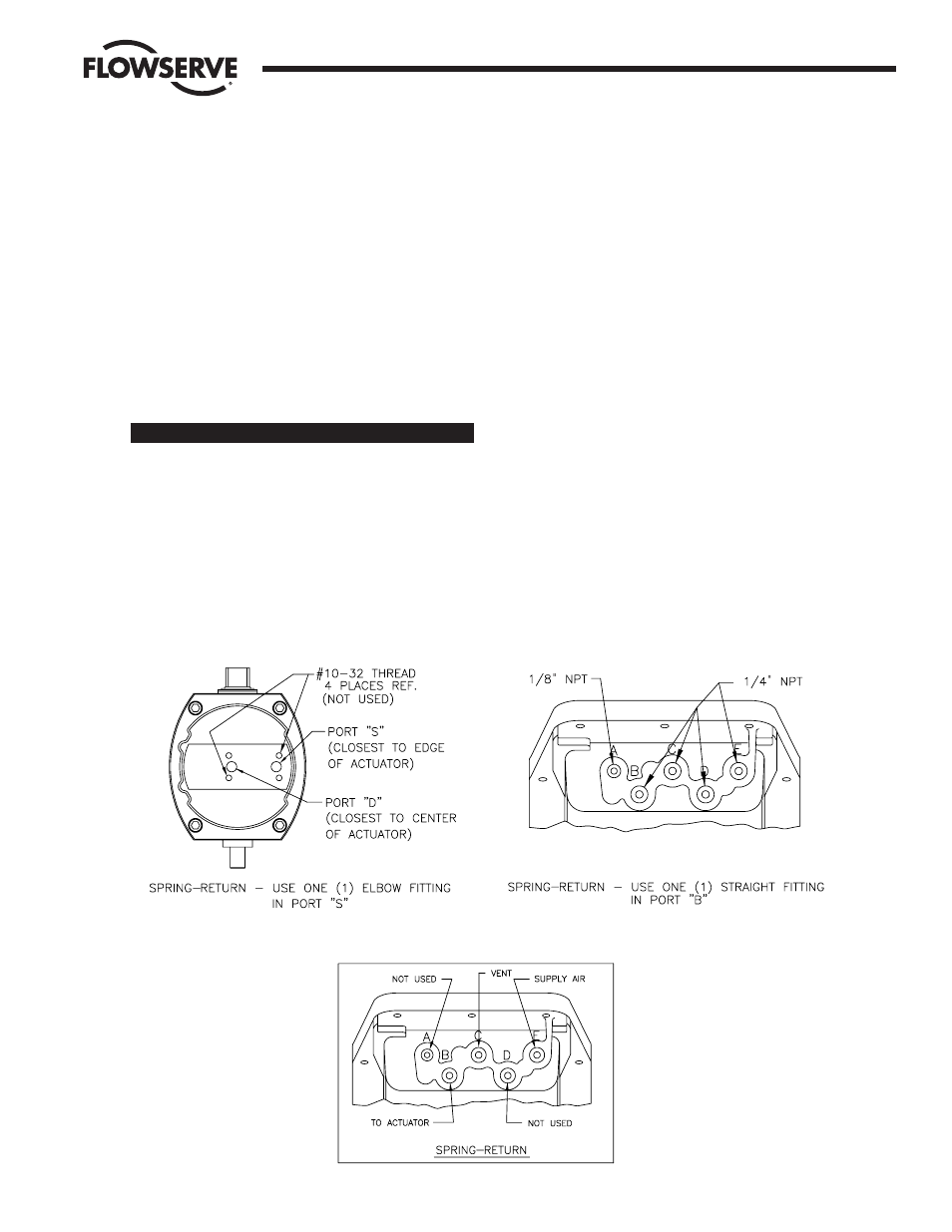
2. Refer to Figure 2. Assemble the elbow fitting(s) to the
actuator. Pipe thread sealant may be used on the threads (do
not allow thread sealant to contaminate the internal air
passages of the M.A.S.). Fluoropolymer tape thread sealant
should not be used.
Actuator Size
Port Thread (NPT)
10 - 20
Z|,"
25 - 40
Z|v"
3. Refer to Figure 3. Assemble the straight fitting(s) to the
Series I90/L90 housing as shown in Figure 3. The thread
sizes are labeled for reference in the figure. Pipe sealant may
be used on the threads (do not allow thread sealant to
contaminate the internal air passages of the M.A.S.).
Fluoropolymer tape thread sealant should not be used.
4. Cut the tubing provided to as short a length as possible that
will still reach comfortably from the Series I90/L90 to the
actuator. Connect the tubes to their respective actuator and
Series I90/L90 ports (reference Figures 2, 3, and 4).
5. Refer to Figure 4 for a diagram of the Series I90/L90 air
connections.
a. Connect the supply air for the actuator (pressure can
range from 30 psi minimum to 100 psi maximum with 80
psi as nominal) to the location labeled “SUPPLY” in the
appropriate sketch.
b. Locations labeled “VENT” are fitted with an orifice plug. A
porous muffler or other fitting designed to reduce exhaust
noise could be substituted if desired. Air must be allowed
to flow freely from these ports. “VENT” locations must
not be plugged under any circumstances.
NOTE: Orifice plug in port “C” can be removed to allow
slightly faster actuation times on larger actuators (sizes
3039 and up).
c. Ports labeled “NOT USED” must remain plugged with the
stainless steel pipe plugs provided.
Flow Control Division
Worcester Controls
Figure 2 – Actuator Fitting Locations
Figure 3 – M.A.S. Fitting Locations
Figure 4 – Air Connections For All I90/L90 M.A.S. Configurations