Worcester controls – Flowserve I90 Series User Manual
Page 17
WCAIM2053
Pulsair Loop-Powered Positioner Modular Accessory System (Series I90/L90)
17
pins that drop into place when the unit is properly
aligned. While holding the piezo valve unit in place,
secure it with the four #6-32 x 1
Z|v" screws (item 8).
5. Mount the push-button control circuit board (item 9)
to the manifold block as shown using two #4-40 x
C|,"
round head screws (item 10). An electronic
connector will be plugged into the bottom of this
circuit board at a later time.
2. WIRING
NOTE: All wiring is to be run smoothly, neatly and away from
any rotating parts and also away from the base/cover flange
joint, using wire ties, if necessary. Use caution to avoid
pinching wires between the base and cover flanges. All wiring
to terminal strip should be inserted only to mid-point of
terminal strip.
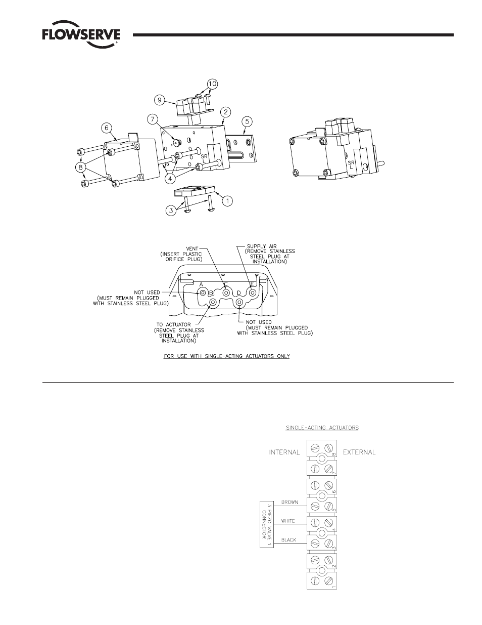
Connect the lead wires from the valve connector plug to the
end terminal strip as shown in the wiring diagram to the
right. The plug is the large tan colored one with three wires
attached to it.
Flow Control Division
Worcester Controls
Figure 16
NOTE: Orifice plug in port “C” can be
removed to allow slightly faster
actuation times on larger actuators
(sizes 3039 and up).