Worcester controls – Flowserve I90 Series User Manual
Page 11
WCAIM2053
Pulsair Loop-Powered Positioner Modular Accessory System (Series I90/L90)
11
Name
Purpose of Function
1.
“YFct”
This function tells the positioner whether the shaft position feedback is linear or nonlinear. In the case of a rotary ball valve,
it should be set to linear. This is because the M.A.S. shaft rotates the feedback potentiometer an equal amount for every
incremental change in stem position.
NOTE: It does not relate to the flow characteristic of the valve.
2.
“init”
This function tells the positioner whether the unit has been calibrated. The proper setting is “oCAY”. If “no” is displayed,
then it is necessary to run the self-calibration procedure described in section III.A.4.c.
3.
“SCUr”
This function tells the positioner whether the low end of the input signal will be 0 mA or 4 mA. Because the positioner
boards being used are loop-powered, they require a minimum of 3.6 mA to operate the circuit board’s power supply and
display. The required setting is “4”.
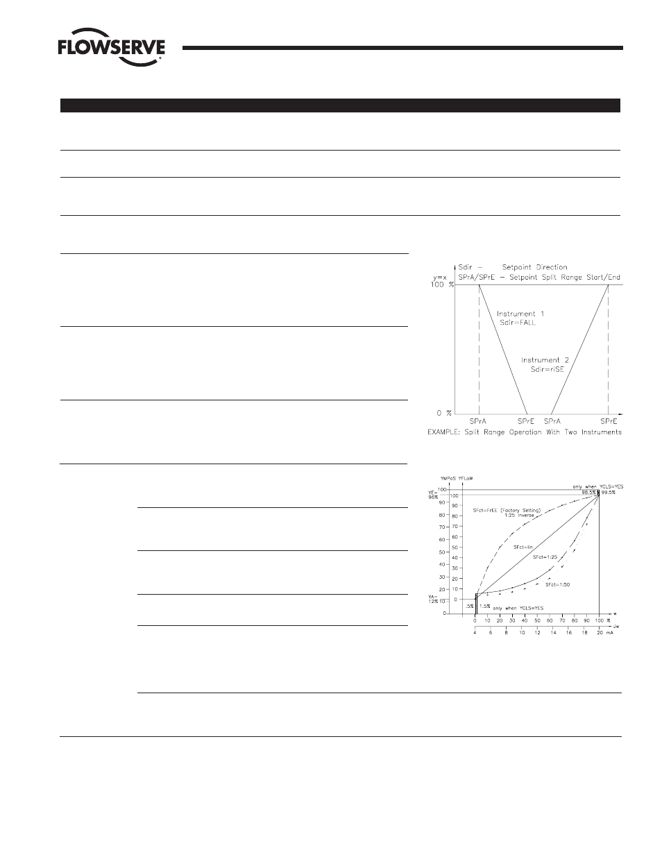
4.
“Sdir”
This function tells the positioner the setpoint direction — is the signal rising or falling? The two possible settings are “riSE”
and “FALL”. For a direct acting response, select “riSE”. The actuator will rotate in the counterclockwise (CCW) direction on
an increasing signal. Refer to Figure 5.
5.
“SPrA”
This function tells the positioner the desired start of the signal range
for the full closed position and is used for split range applications.
The setting can be anywhere from 0 to 100% of the signal range in
0.1 percent increments. This function is used in conjunction with
“SPrE”. The “SPrA” setting should be less than the “SPrE” setting.
See Figure 5.
6.
“SPrE”
This function tells the positioner the desired end of the signal range
for the full open position and is used for split range applications.
The setting can be anywhere from 0 to 100% of the signal range in
0.1 percent increments. This function is used in conjunction with
“SPrA”. The “SPrE” setting should be greater than the “SPrA”
setting. See Figure 5.
7.
“tS” -
This function tells the positioner the desired rate of response to a
step change in signal. It can be used to slow the positioning of the
actuator. Possible settings are “AUto” or 0 to 40 seconds in 1 second
increments. With “AUto” selected, the positioner chooses the best
response. The factory default setting is 0 seconds.
8.
“SFct”
This function tells the positioner the desired shaft positioning
characteristic with respect to input signal. The four possible settings
are “Lin”, “1:25”, “1:50”, and “FrEE”. Refer to Figure 6.
“Lin” causes the shaft position to vary in a linear fashion as the input
signal changes (i.e. if the signal is at 50 percent, the shaft position
will be at 50 percent of the selected operating range).
“1:25” causes shaft position to change in an equal percentage ratio of
1 to 25 (i.e. the shaft will rotate less at the lower end of the signal
range when given an equal change in input signal).
“1:50” causes shaft rotation to change in an equal percentage ratio
of 1 to 50.
“FrEE” allows 11 setpoint vertices to be set. In this way, a custom
shaft positioning characteristic can be entered. There is a vertices set
(data point) at 4 mA and then every 1.6 mA up to and including 20 mA. The vertices are displayed as “SL 0” to “SL 10” and
will only be displayed when “FrEE” is chosen as the setting. Use the “UP”, “DOWN”, and “FUNCT” buttons to select and
change the vertices settings.
The vertices are shown as percent of shaft rotation for the established operating range and have a resolution of 0.1 percent.
The factory default settings for the “FrEE” setting are the inverse of the 1:25 characteristic. The factory default for the “SFct”
function is “Lin”.
9.
“dEbA”
This function tells the positioner the desired positioner deadband. The possible settings are “Auto” or 0.1 to 10.0 percent of
signal span in increments of 0.1 percent. When “AUto” is selected, the deadband is constantly adapted to the operating
conditions. It is suggested that this setting be used unless special conditions exist (such as a randomly noisy signal) that
cause the process to become unstable intermittently. The factory default setting is “AUto”.
Flow Control Division
Worcester Controls
Figure 5 – Split Ranging
Figure 6 – Flow Characteristics