Worcester controls – Flowserve I90 Series User Manual
Page 12
12
Pulsair Loop-Powered Positioner Modular Accessory System (Series I90/L90)
WCAIM2053
Name
Purpose of Function
10. ”Ydir”
This function tells the positioner the desired direction of action of the display when using it for position output indication.
The two possible settings are “riSE” and “FALL”. The factory default setting is “riSE”. When “riSE” is selected, the displayed
output will increase as the actuator shaft rotates CCW. When “FALL” is selected, the displayed output will decrease when the
shaft rotates CCW.
11. ”YnrM”
This function tells the positioner how the displayed position output should be standardized. The two choices are “MPoS” and
“FLoW”. “MPoS” shows the actual actuator shaft position dictated by the “YA” and “YE” functions. For example, with “YA”
set to the 25% open position and “YE” set to the 75% open position, the displayed position will be 0 at 25% open and 100 at
75% open. If “YA” and “YE” are set to 0 and 100 percent, respectively, then it is recommended that “MPoS” be selected. If
“YA” and “YE” are set to values other than 0 and 100 percent, then it is recommended that “FLoW” be selected. The factory
default is “MPoS”. Refer to Figure 6.
12. ”YA”
This function tells the positioner the desired lower limit for shaft position at the start of the signal range. It can be set to a
value from 0.0 to 100.0 in increments of 0.1 percent. The factory for this function is 0.0 percent. Refer to Figure 6.
13. “YE”
This function tells the positioner the desired upper limit for shaft position at the end of the signal range. It can be set to a
value from 0.0 to 100.0 in increments of 0.1 percent. The factory for this function is 100.0 percent. Refer to Figure 6.
14. ”YCLS”
This function tells the positioner whether tight valve shutoff is desired when the input signal reaches the low end of its range and
whether the valve will fully open when the input signal reaches the upper end of its range. It is significant when the “YA” function
is set to a value other than 0.0 percent. The two choices are “YES” and “no”; “no” is the factory default. Refer to Figure 6.
15. “Afct”
This function is used to set alarm limits. It is not available in the unit at this time.
16. “A1”
This function sets the alarm 1 threshold. It is not available in the unit at this time.
17. “A2”
This function sets the alarm 2 threshold. It is not available in the unit at this time.
18. “Fct”
This function sets the alarm output function. It is not available in the unit at this time.
19. “PrSt”
This function is an indicator of whether the factory settings have been altered. The two possible indications are “no” and
“oCAY”. “oCAY” indicates that all the factory defaults are being used. If “no” is displayed and it is desired that the factory
settings be restored, then press the “FUNCT” button momentarily to lock in the display. Then press the “UP” button for greater
than 5 seconds until the display flashes “oCAY”. The default settings are now loaded into memory. Refer to Section III.A.5.
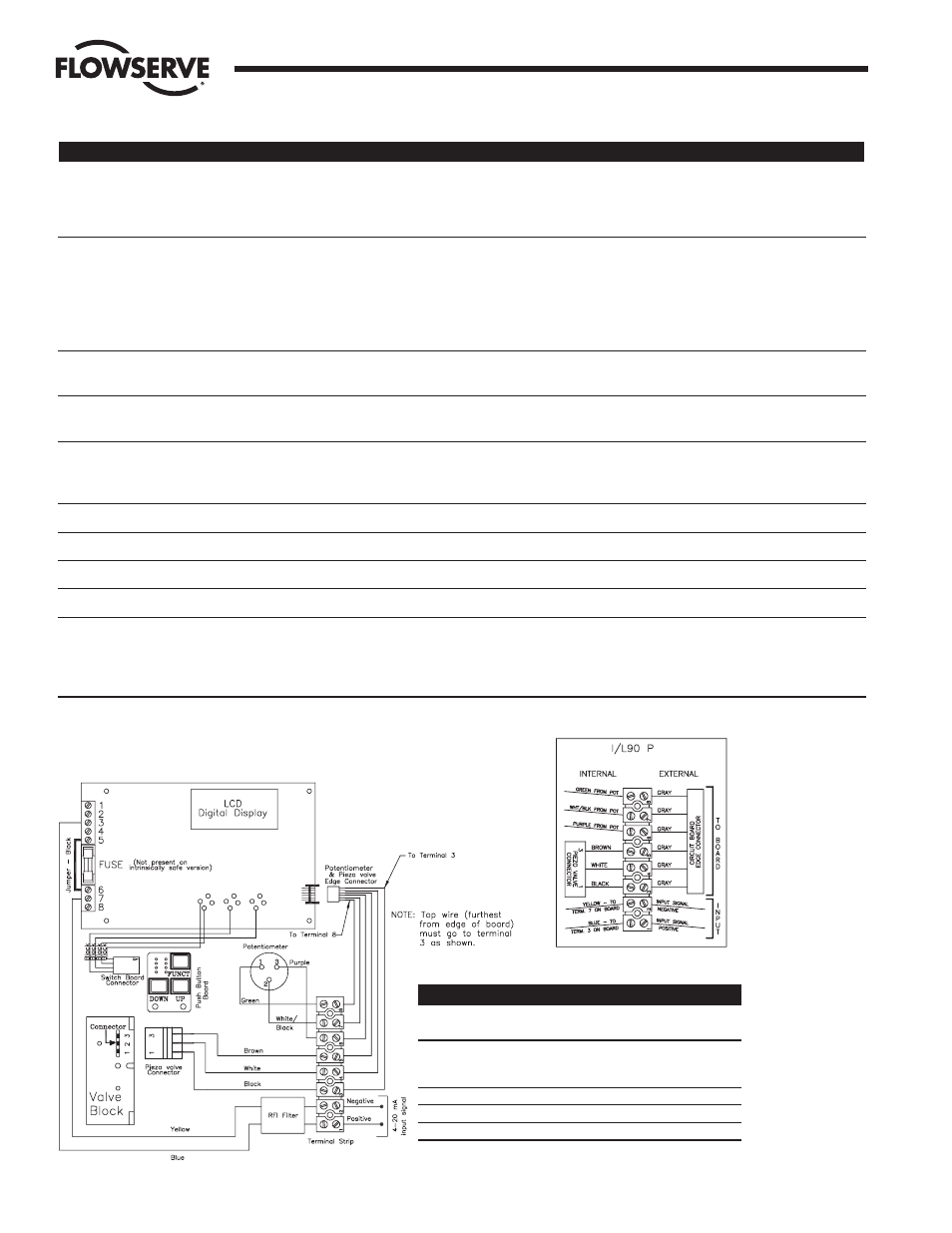
7. WIRING DIAGRAMS – Reference General Arrangement Drawing Below
General Wiring Arrangement
Flow Control Division
Worcester Controls
Modifications for “Fail-Open” Operation
Actuator Actuator Wiring
Mounting
Size
Modifications
Notes
In-line
10-20
Swap Green and
Actuator is
Purple Wires at
Inverted
Terminals 6 and 8
In-line
25-40
No Change
—
Cross-line
10-20
No Change
—
Cross-line
25-40
No Change
—
NOTE: For wiring of M2 switch,
dual potentiometer or
4-20 mA output
transmitter options,
refer to Sections III.D.3,
III.E.2, or III.F.2
respectively.