Worcester controls – Flowserve I90 Series User Manual
Page 21
WCAIM2053
Pulsair Loop-Powered Positioner Modular Accessory System (Series I90/L90)
21
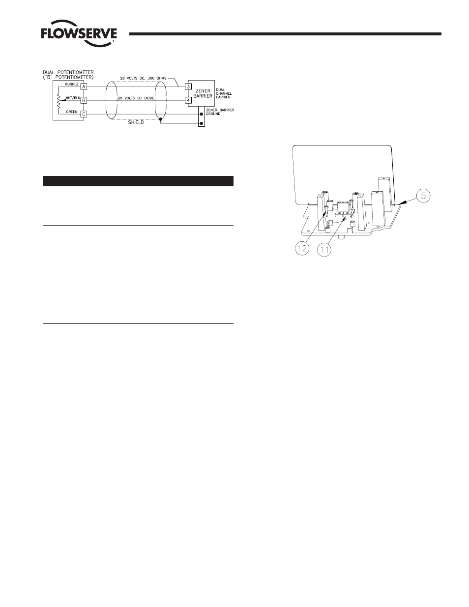
IMPORTANT: Shielded cable must be used for each intrinsically safe
circuit and, for zener barriers, the shield must be connected to a
zener barrier ground.
3. TROUBLESHOOTING POTENTIOMETER
Problem
Possible Cause(s)
Solution
Indicates
Green and Purple
Check wiring per
backwards
wires reversed
Section III.E.2.
Reverse-acting Reverse
green
and
actuator
purple wires.
Indication not
Gears slipping
Check gear tooth
consistent
engagement of face
gear (approximately
Z|zn")
Pinion gear set
Recalibrate and
screw loose
tighten set screw.
Indication not
Potentiometer needs
Calibrate
correct
to be calibrated
potentiometer per
Section III.A.4.
M.A.S. shaft turned
Recalibrate for new
more than 90 degree
quadrant.
F.
TWO-WIRE 4 to 20 mA OUTPUT TRANSMITTER OPTION
The 4-20 mA output board has been designed for use in the
Pulsair Positioner unit as a position feedback option which will
operate as a two-wire loop-powered transmitter. The circuit can
operate on 12 or 24 Volts DC, or in intrinsically safe systems.
Provided on the board is a two-pin connector for wiring the board to
the Pulsair terminal strip and a three terminal strip for connection to
the 1000 ohm feedback “B” pot (rear) of the dual potentiometer.
NOTE: Dual potentiometer option (coded P or 5) and 4-20 mA
output transmitter option (coded 4) cannot both be ordered at the
same time. The 1000 ohm Feedback “B” pot (rear) for the 4-20
mA transmitter board connects to the terminal strip on
transmitter circuit board.
1.
ASSEMBLY (Refer to Figure 22)
a. Dual Potentiometer
1. Remove single feedback pot and bracket, if installed,
and install dual pot and bracket provided. Use
existing face gear on shaft, if installed (refer to
section III.E.1).
b. 4-20 mA Output Transmitter Board
1. The circuit board (item 11) is mounted to the Pulsair
baseplate with two #4 x
C|," self-tapping screws (item
12). The terminal strip on the board should be
oriented toward the Pulsair shaft.
2. WIRING (Refer to General Wiring Arrangement on next page.)
NOTE: All wiring is to be run smoothly and neatly and away
from any rotating parts, using wire ties, if necessary. Use
caution to avoid pinching wires between the base and cover
flanges. All wiring to terminal strip should be inserted only to
mid-point of terminal strip.
a. Wire the 4-20 1000 ohm “B” (rear) potentiometer of the
dual potentiometer to the circuit board terminal strip as
follows:
Green wire to
TB-1 terminal 1
White/Black wire to
TB-1 terminal 2
Purple wire to
TB-1 terminal 3
A two-wire connector assembly connects the signal loop
to the circuit board. Connect the red wire to Pulsair
terminal A (positive) and the black wire to Pulsair terminal
B (negative).
Flow Control Division
Worcester Controls
Figure 22
NOTE: Terminal strips, shaft and potentiometer
assembly not shown for clarity.