Iii. operating and maintenance instructions, Worcester controls – Flowserve I90 Series User Manual
Page 6
6
Pulsair Loop-Powered Positioner Modular Accessory System (Series I90/L90)
WCAIM2053
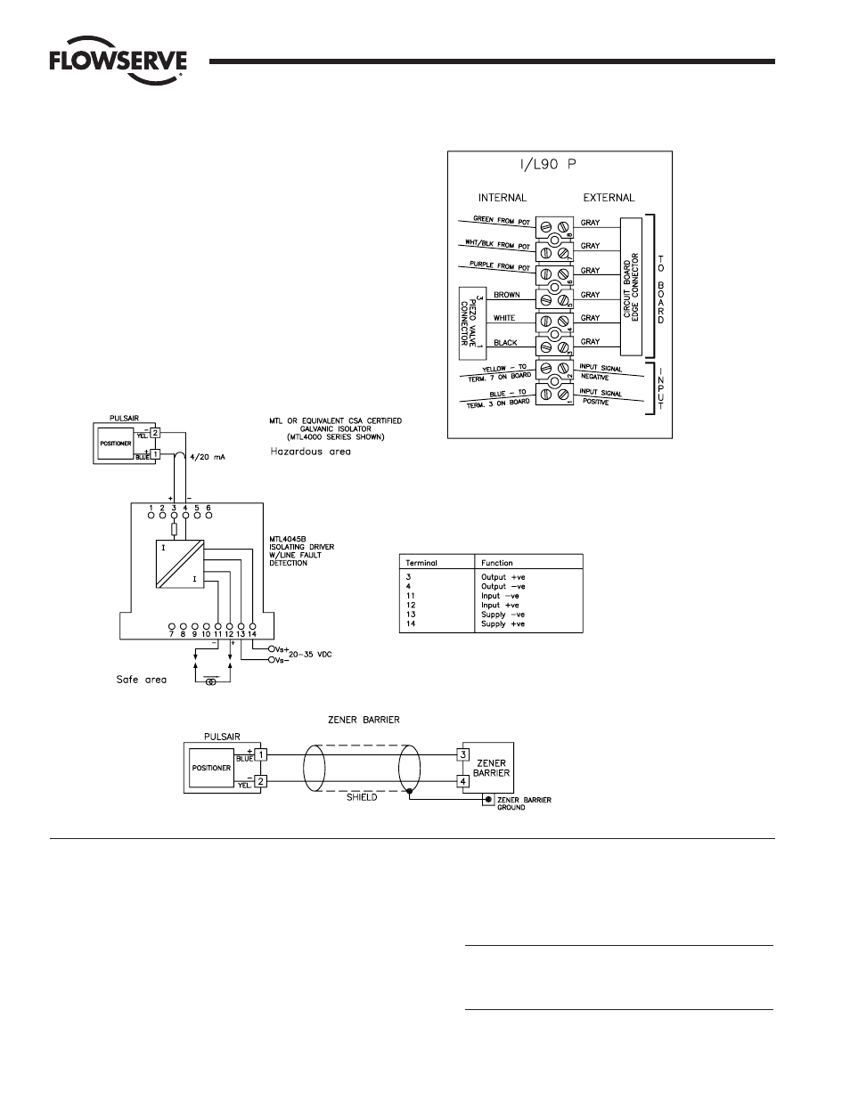
C. WIRING CONNECTIONS
1. Connect 4-20 mA signal to terminals 1 and 2 as shown in
wiring diagram to the right. If unit is intrinsically safe,
connection must be made through a CSA certified zener
barrier or a CSA certified galvanic isolator as shown below.
NOTE: Terminal numbers and polarity. Shielded cable should
be used for all connections. For zener barriers, the shield
must be connected to a zener barrier ground.
For switch, potentiometer and feedback option wiring, see
Sections III.D.3, III.E.2 and III.F.2 respectively.
NOTE: All wiring to terminal strip should be inserted only to
mid-point of terminal strip.
2. Please review cautions and background information below
and on pages 7 and 8 before proceeding with calibration
section III.A.4. on page 9.
III. OPERATING AND MAINTENANCE
INSTRUCTIONS
A. POSITIONER
The Worcester/McCANNA Pulsair Loop-Powered Positioner circuit
board is designed for use with the Worcester Series 90 Modular
Accessory System. It is a microprocessor-controlled, loop-powered
circuit capable of high-resolution control. The circuit is user-
programmable, allowing a new level of flexibility and performance.
IMPORTANT: Instructions for powering up the Pulsair are located
on page 9, Section 4 Calibration. It is highly recommended that
the information be reviewed before turning on power supply.
1. POSITIONER SPECIFICATIONS AND TECHNICAL DATA
CAUTION: The voltage and current to the signal input circuit
must never exceed 30 volts and/or 40 mA. Please observe
proper signal polarity as marked in these instructions and
on the wiring diagram located inside the M.A.S. cover.
Flow Control Division
Worcester Controls