Worcester controls – Flowserve I90 Series User Manual
Page 20
20
Pulsair Loop-Powered Positioner Modular Accessory System (Series I90/L90)
WCAIM2053
E. FEEDBACK POTENTIOMETER AND POTENTIOMETER OPTIONS
The Pulsair I90/L90 M.A.S. requires a precision 5000 ohm
potentiometer to provide feedback representing the position of the
M.A.S. shaft to the positioner circuit board. In addition, a second
potentiometer can be provided (in the form of a dual
potentiometer) to allow remote monitoring of the shaft position.
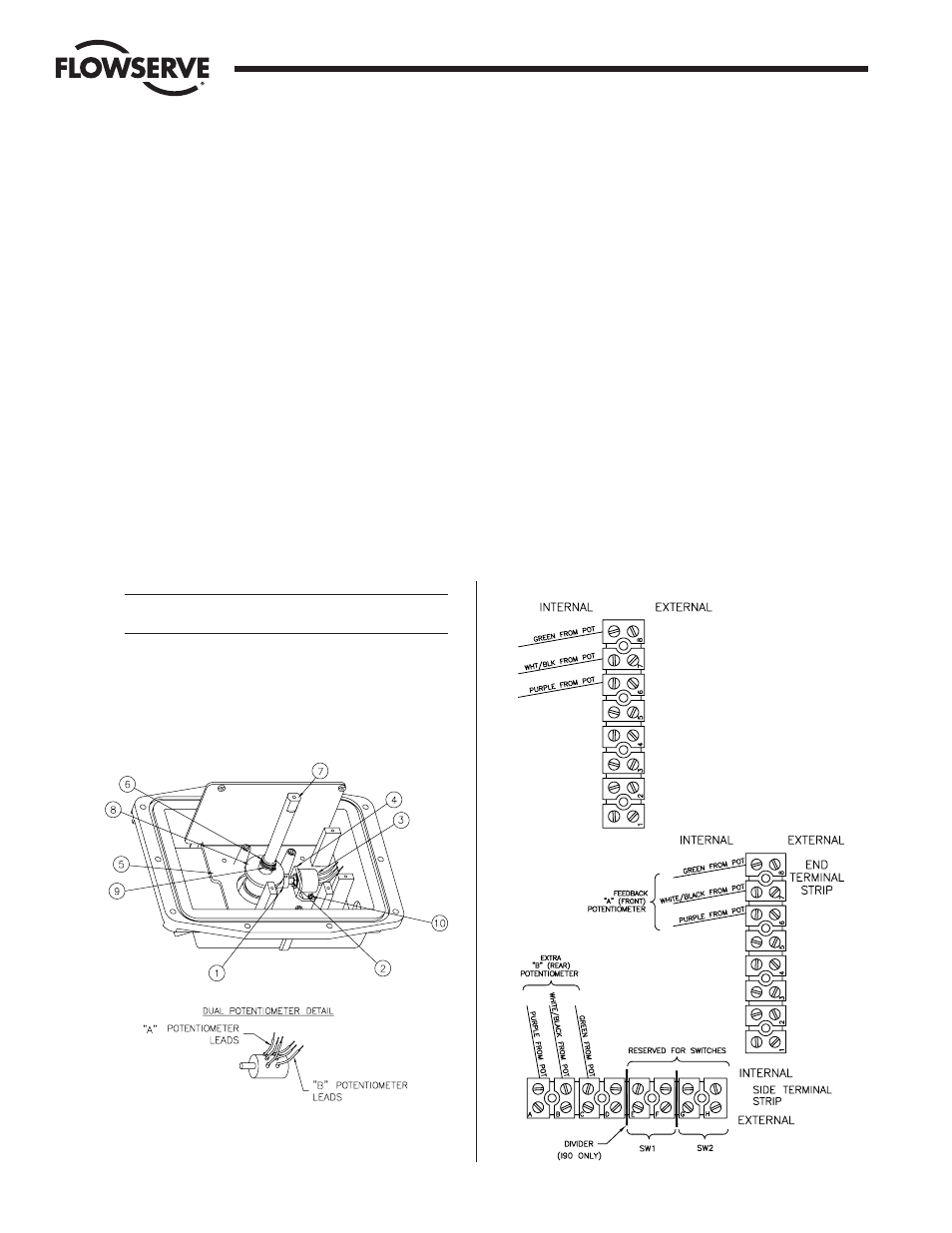
1. ASSEMBLY (See Figure 21)
Note: Assembly is the same for both dual potentiometer and
single potentiometer.
a. With the potentiometer (item 3) mounted to the
potentiometer bracket (item 4) and the pinion gear (item
1) loosely fitted to the potentiometer shaft (item 2),
mount the potentiometer bracket (item 4), if not already
mounted, to the baseplate (item 5) using two #8-32 x
B|zn
screws (item 10) provided.
b. Remove the upper snap ring (item 6) from the shaft (item
7). Use care to avoid deforming it permanently.
c. Slide the face gear (item 8) onto the shaft, teeth facing
down and secure with the snap ring (item 9) provided.
NOTE: The face gear utilizes a friction fit to the shaft. For
best results, wipe off any lubricant that may be on the
shaft before sliding on the face gear.
CAUTION: Do not overstretch the snap ring, use
minimum opening to allow it to slip over the gear.
d. Replace the upper snap ring (item 6).
e. Adjust the potentiometer pinion gear so that there is
approximately
Z|zn" tooth engagement between the face
and the pinion gear and tighten the pinion gear set screw.
2. WIRING
NOTE: All wiring is to be run smoothly and neatly and away
from any rotating parts. Use caution to avoid pinching wires
between the base and cover flanges. All wiring to terminal
strips should be inserted only to mid-point of terminal strips.
a. For Feedback (Single) Potentiometer – Connect the
potentiometer lead wires to the end terminal strip as
indicated by the wiring diagram below.
b. For Dual Potentiometer – Connect the lead wires from the
feedback “A” (front) potentiometer to the end terminal
strip as indicated by the wiring diagram below.
The three leads from the “B” (rear) potentiometer will be
connected to the side terminal strip as indicated by the
wiring diagram below.
IMPORTANT: Voltage limit of “B” potentiometer is 30 volts
maximum.
c. Route the wires neatly and use wire ties, if necessary. Be
certain that the wires will not get fouled on the shaft when
it rotates.
d. “Fail-Open” operation may require wiring modifications.
For details, see Table in Section III.A.7, Wiring Diagrams.
NOTE: FOR
INTRINSICALLY SAFE
SYSTEMS ONLY.
All inputs/outputs
(“external” wiring
connections) must be
run through a CSA
certified zener barrier:
Flow Control Division
Worcester Controls
Figure 21
Feedback (Single) Potentiometer Only
Dual Potentiometer