Worcester controls – Flowserve I90 Series User Manual
Page 19
WCAIM2053
Pulsair Loop-Powered Positioner Modular Accessory System (Series I90/L90)
19
2. Assemble the switches and adjustment plate to the
baseplate (item 4) as shown below, using the “loose”
#4-40 x 1" screw and the #4-40 x
C|," screw (item 5)
and #4 washer (item 6). Move the adjustment plate to
a middle position and tighten the screws.
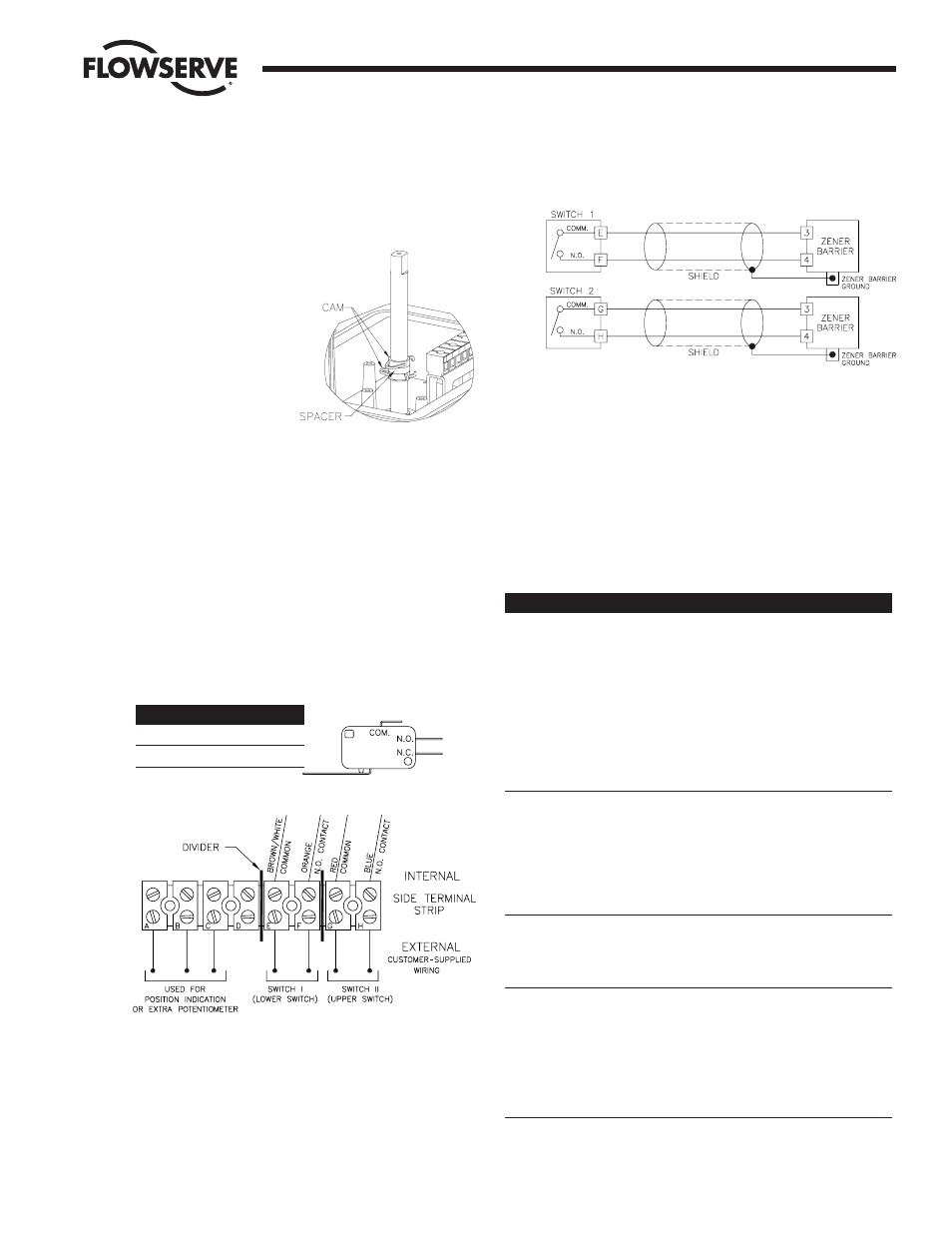
2. CAMS
Assemble the first spring
cam, the spacer and second
spring cam. To work the
spring cam down the shaft,
squeeze the two protrusions
and turn. See Figure 20.
3. WIRING
NOTE: All wiring is to be run
smoothly and neatly and
away from any rotating
parts, using wire ties, if necessary. Use caution to avoid
pinching wires between the base and cover flanges. All wiring
to terminal strip should be inserted only to mid-point of
terminal strip.
a. The wire leads will be connected to the switches as
provided. Pay close attention to the switch labels,
schematics, wire colors, etc. when wiring the switches.
Switches are to be wired to the side terminal strip as shown
in wiring diagram below. The end terminal strip is for
connecting the potentiometer and the positioner circuitry
only. See Figures 12 and 13 for location of terminal strips.
For Intrinsically Safe (I90) version only, dividers are to be
in place between terminals D and E, F and G.
b. Route the wires neatly and use wire ties if necessary. Be
certain that the wires will not get fouled on the shaft when
it rotates.
NOTE: FOR INTRINSICALLY SAFE SYSTEMS ONLY.
All inputs/outputs (“external” wiring connections) must
be run through CSA certified zener barriers.
IMPORTANT: Shielded cable must be used for each
intrinsically safe circuit and for zener barriers, the shield
must be connected to a zener barrier ground.
4. OPERATION
a. Once the M.A.S. unit has been assembled and connected
to the actuator, the switch cams can be set per user’s
requirements. Normally switch I indicates “closed” and
switch II indicates “open”.
b. The unit should be operated to ensure that switch
actuation occurs at the end of rotation (or in whatever
position is desired by the customer) repeatably.
5. TROUBLESHOOTING
Problem
Possible Cause(s)
Solution
Switches do not
Improper cam settings
Reset cams.
indicate at proper
positions
Switch does not
Switch too far
Loosen the
actuate (never
from cam
adjustment plate
trips)
screws and rotate
switches towards
shaft until actuation
is correct — retighten
screws.
Switch does not
Switch too
Loosen the
reset (always
close to cam
adjustment plate
tripped)
screws and rotate
switches away from
shaft until actuation
is correct — retighten
screws.
No indication at
Broken, defective, or
Check wiring with
terminal strip
misplaced wire
appropriate wiring
diagram per
Section III.D.3.
Cams not aligned
Cams/spacers in
Check and
with switch arms
wrong order
reassemble cams per
Section III.D.2.
Cams not pushed
Push cams into
into place
proper locations —
align with switch
arms.
Flow Control Division
Worcester Controls
Figure 20
Switch
Com.
N.O.
I
Brn/Wht
Orange
II
Red
Blue