Worcester controls – Flowserve I90 Series User Manual
Page 18
3. OPERATION
The piezo valves are controlled by the positioner circuitry. The
valve block contains two separate valves. One allows air to
enter the actuator, the other allows air to vent from the
actuator. Opening, closing and holding are accomplished by
energizing the appropriate combination of valves. The unit is
fail-safe on loss of air pressure or electrical signal.
4. TROUBLESHOOTING
Problem
Possible Cause(s)
Solution
Air leak between
Loose piezo valve unit
Tighten piezo valve
piezo unit/block
screws.
or between
Gasket out of position
Remove manifold
block/housing
block, realign gasket
and reattach manifold
block.
Defective gasket
Contact Flowserve
for replacement.
Rough surfaces on
Contact Flowserve
manifold block
for replacement.
Actuator not
Valve Block
operating
Power supply not
Check power supply.
connected/not working
3.6 mA minimum is
required for
operation.
Defective lead wires
Check leads with
ohmmeter or try new
lead wires.
Defective piezo valve
Contact Flowserve.
or manifold block
Problem with
Contact Flowserve.
positioner board
Actuator
High valve torque
Disconnect valve and
check operation/
torque.
Air supply not
Check supply air
connected/low pressure piping and pressure.
Tubing connections to
Check M.A.S. air
M.A.S. not correct
connections.
Debris in piezo valve
Remove and clean
or manifold block
manifold block; do
not disassemble
piezo valves (contact
Flowserve); check
filtering per
Section III.C.
No obvious cause(s)
Disconnect M.A.S.
from actuator; test
each unit separately.
D. SWITCH OPTIONS
A mechanical switch option is available in the Pulsair Series
I90/L90 Modular Accessory System. The switches can be used to
provide actuator position indication or to control other equipment.
The option always available (regardless of other options) is:
M2 – Two Single-Pole Double-Throw Mechanical Switches
The standard switches provided will be gold contact types suitable
for low-power applications (120/240 VAC, 1A). Switches capable
of handling higher currents are available through Flowserve.
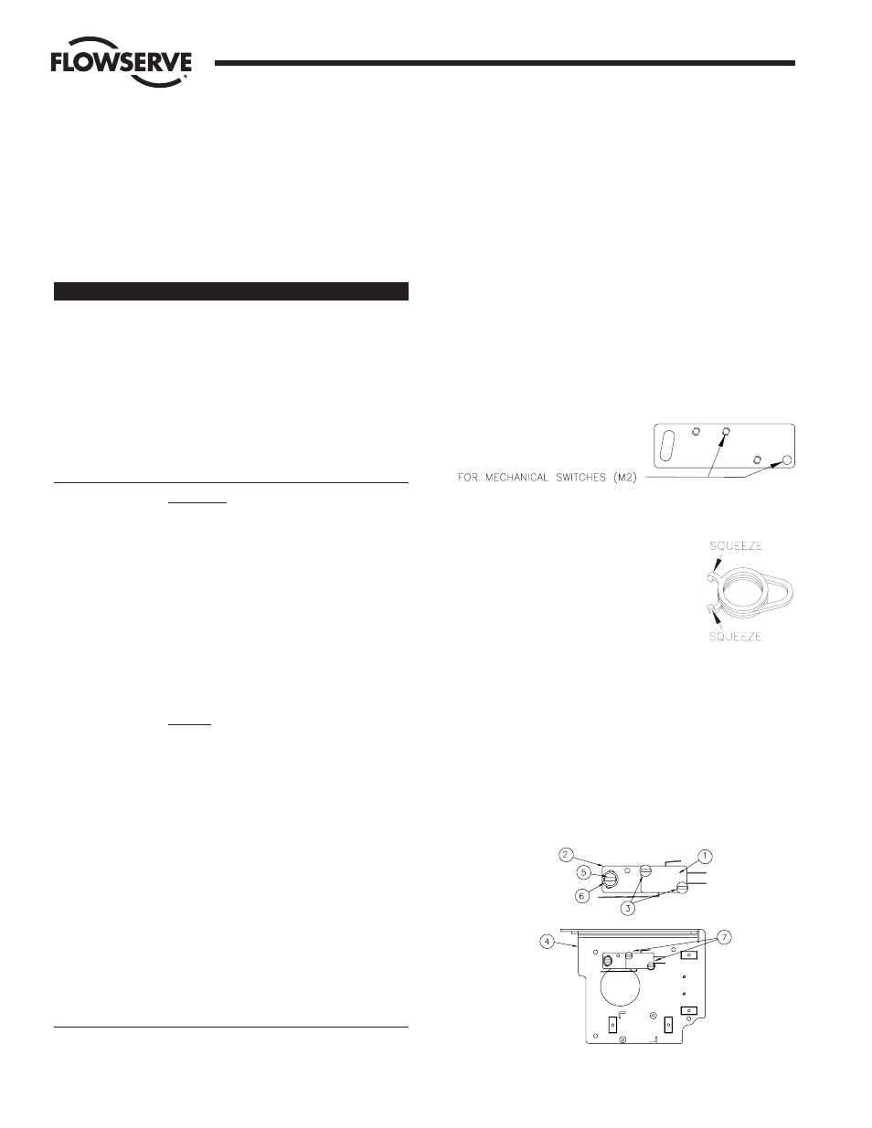
An “Adjustment Plate” is used to mount the single pole
mechanical switches to the baseplate. Mechanical switches are
mounted to the adjustment plate and set to a middle position —
not rotated towards or away from the shaft. There are two sets of
mounting holes in the adjustment plate, use the appropriate set as
shown below in Figure 17. Their use will be detailed later.
The cams used to actuate the switches offer
unlimited positioning without the use of tools.
These cams are essentially “wrap-springs”
and grip the shaft tightly enough to prevent
accidental rotation. Squeezing together the
two small protrusions from the cam, as
shown in Figure 18, loosens the spring and
allows adjustment. Needle nose pliers may
prove to be helpful when installing the cams,
but are not required.
1. ASSEMBLY
a. M2 – TWO SPDT MECHANICAL SWITCHES
1. Stack two switches (item 1) and attach to the
adjustment plate (item 2), as shown in Figure 19,
using two #4-40 x 1" screws (item 3) provided. Note:
One of the screws will thread into a tapped hole in the
adjustment plate while the other engages a clearance
hole without threads.
Flow Control Division
Worcester Controls
Figure 17
Figure 18
Figure 19
18
Pulsair Loop-Powered Positioner Modular Accessory System (Series I90/L90)
WCAIM2053