Worcester controls – Flowserve I90 Series User Manual
Page 14
14
Pulsair Loop-Powered Positioner Modular Accessory System (Series I90/L90)
WCAIM2053
B. HOUSING ASSEMBLY
The housing consists of the base, cover, shaft, baseplate and
associated hardware. The housing is assembled as received from
Flowserve. For ease of maintenance, assembly instructions will be
provided here.
1. COVER
CAUTION: Use care to avoid damaging the machined flange
surface of the cover.
a. Apply a light coat of Cindol 2321 lubricant (or other
bearing grease) to the shaft hole.
b. Assemble the captive type cover screws through the
flange holes. The screws must be turned through
approximately
Z|v" of thread until they reach the clearance
diameter and remain loose in the cover. Use caution to
avoid cross-threading these screws. Refer to Figure 8.
c. Check to see that the shaft seal has been installed as
shown in Figure 9.
CAUTION: When assembling cover to base, be sure wires
are away from any rotating parts and are not pinched
between cover and base flanges. Relubricate the shaft hole
anytime cover is removed and replaced. To avoid damaging
the cover hole finish and binding the shaft to cover, check
the top of the shaft for burrs or impact damage before
installing or removing cover.
2. BASE
CAUTION: Use care to avoid damaging the machined flange
surface of the base.
a. Check to see that the shaft seal and bearing have been
installed as shown in Figure 9.
b. Apply a light coat of bearing lubricant to the shaft hole.
c. Insert the shaft through the shaft hole in the base from
the inside. The shaft fits through this hole with minimal
clearance — care must be taken to avoid damaging the
bearing surfaces or causing the shaft to gall.
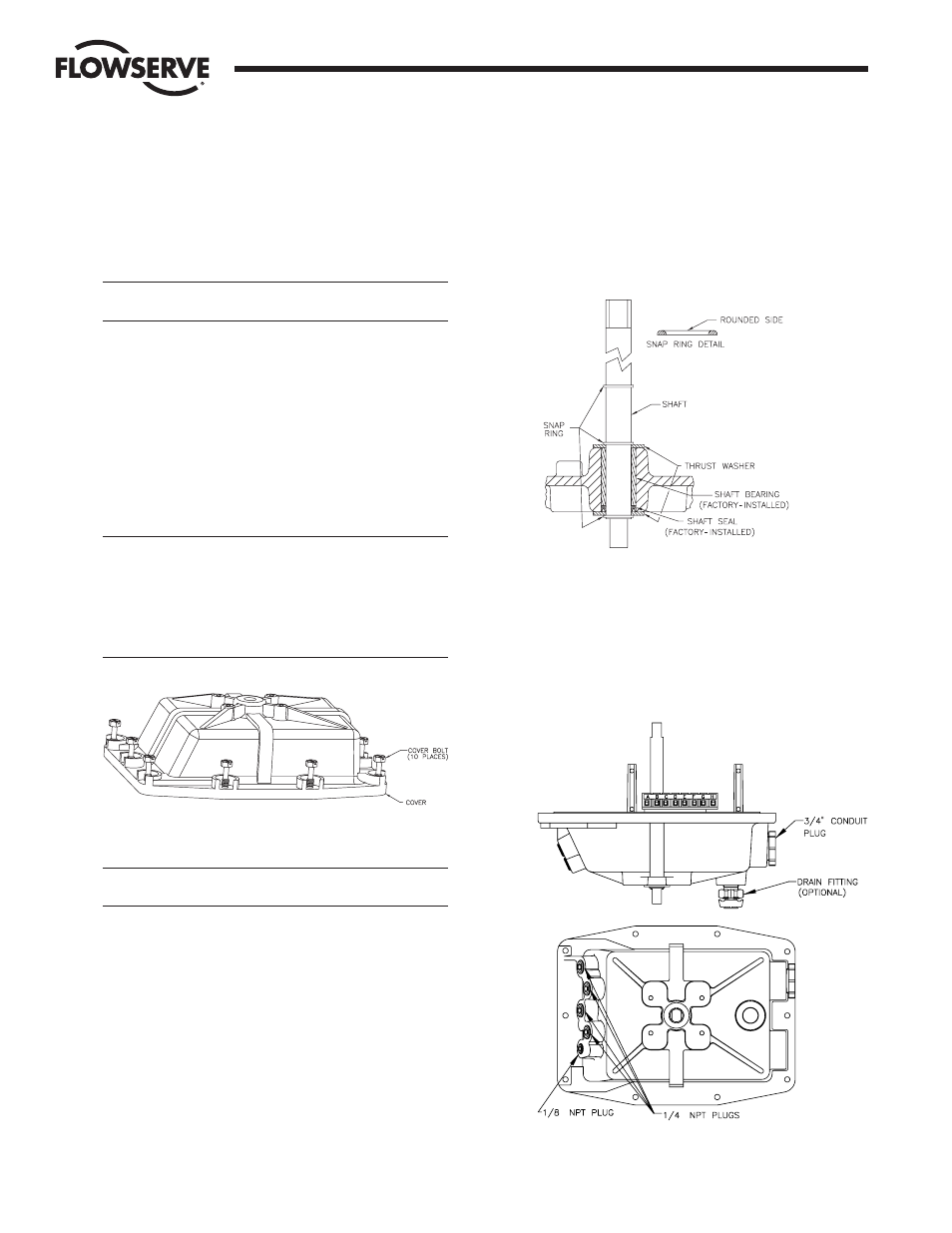
d. Place one of the nylon thrust washers onto the shaft end
protruding outside the base. Assemble one of the snap
rings to the shaft in the groove below this thrust washer
(rounded side towards thrust washer — see detail).
e. Place a second nylon thrust washer over the shaft and
into place against the shaft boss on the inside of the
base. Secure the shaft in place with a second snap ring in
the groove adjacent to the second thrust washer (rounded
side towards thrust washer — see detail).
f.
Place the third snap ring into the upper groove as shown
in Figure 9.
g. If the base is machined to accept a breather/drain fitting as
shown in Figure 10, then the boss on the bottom of the
base near the electrical conduit connection bosses will be
tapped with
C|," NPT threads. If this boss is tapped, the
breather/drain fitting must be installed. The use of
fluoropolymer tape or other thread sealant is recommended
prior to installing this fitting into the boss.
Flow Control Division
Worcester Controls
Figure 8
Figure 9
Figure 10
"
"